Xtralis Pty Ltd XCC Product Guide
www.xtralis.com 9
3 Wiring Connections
3.1 Termination Card
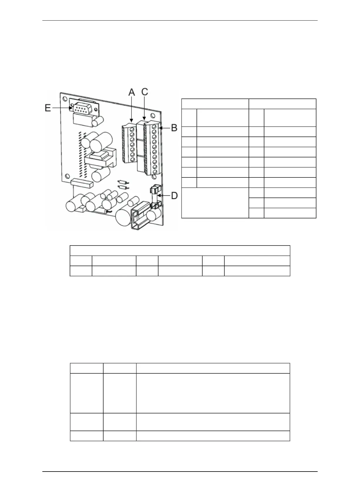
The Termination Card acts as the interface for PC configuration, Power Supply Terminals and Relay
Terminals.
Terminal A Terminal B
1 FIRE-ALARM
(NO)
1 Bias (-) (GND)
2 FIRE-ALARM (C) 2 Reset (-) (GPI)
3 PRE-ALARM (NO) 3 Reset (+) (GPI)
4 PRE-ALARM (C) 4 Bias (+)
5 FAULT (NO) 5 LED (-) (GND)
6 FAULT (C) 6 LED(+)
7 FAULT (NC) 7 Power (-)
8 Power (+)
9 Power (-)
10 Power (+)
Legend
A Terminal A C Relays E Programming Socket
B Terminal B D 1.6A Fuse
Figure 3-1: Termination Card
3.2 Relay Terminals
There are three relays designated Fault, Pre-Alarm and Fire. The relays can be used to connect to the fire
alarm control panel or to activate external devices. The Fire-Alarm and Pre-Alarm relay states are non-
energized and the Fault relay set to energized on power up (de-energized on Fault).
3.3 Relay settings and conditions to change states
Table 3-1: Default relay settings and conditions to change state
Relay # Relay Condition for relay to change state
1 Fault This relay is de-energized when one of the following
conditions occur:
l Fault found on detector
l Air flow normalization is initiated
l System isolation is initiated
2 Pre-Alarm This relay is energized when the unit detects a potential fire
event.
3 Fire This relay is energized once the unit detects a fire.