Xtralis Pty Ltd XCC Product Guide
www.xtralis.com 11
3.5 Programming Socket
The 9 pin programming socket on the termination card provides the communication interface between the
detector and a PC running Xtralis VSC. Connect the PC to the detector using a RS232 data cable directly to
the 9 pin programming socket.
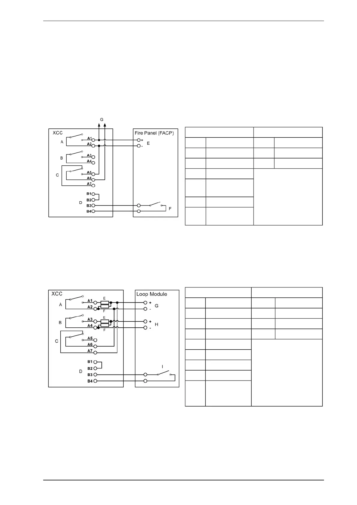
3.6 Typical Wiring to a Fire Panel with an EOL Resistor
The diagram below shows the correct way to wire XCC detectors to a conventional fire alarm control panel
(FACP). It also shows where an End Of Line (EOL) resistor is correctly installed.
Legend Line Impedance
A Fire Relay EOL Quiescent
B Pre-Alarm Relay Short Fire Alarm
C Fault Relay Open Fault
D GPIInput
E Conventional
Loop Input
F Reset Contact
G To next detector
or EOLresistor
Figure 3-3: Typical wiring to a fire panel with EOL resistor
3.7 Wiring to an Addressable Loop Module
This wiring example is for wiring XCC detectors to a typical Input/Output Loop module (3 input 1 output).
These are example drawings. Refer to the appropriate product manual for the exact wiring details of the third
party equipment.
Legend Line Impedance
A Fire Relay EOL Quiescent
B Pre-Alarm Relay Fire Fire Alarm
C Fault Relay Open Wiring Fault
D GPIInput Short Detector Fault
E Fire
F EOL
G Input 1
H Input 2
I Output
(configured on
reset)
Figure 3-4: Typical wiring to an input/output loop module