XCC Product Guide Xtralis Pty Ltd
10 www.xtralis.com
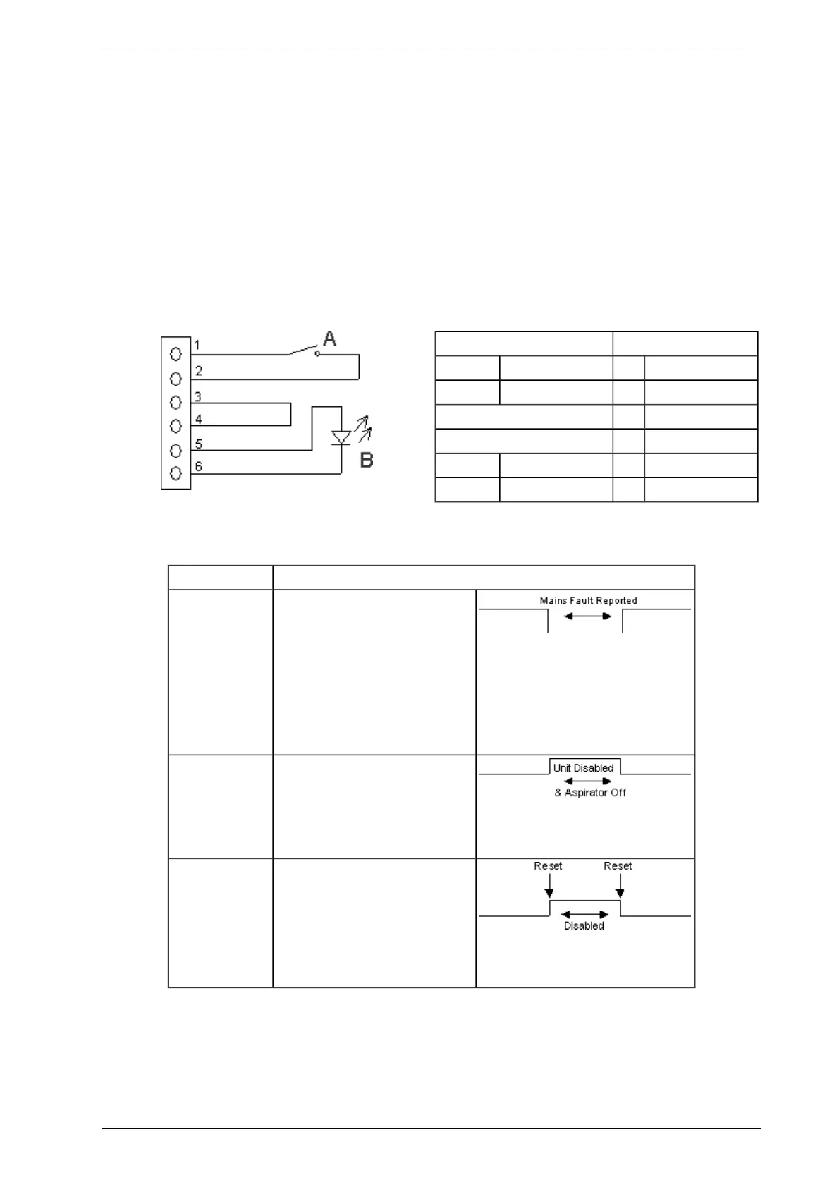
3.4 Auxiliary / GPI Terminals
The Reset (GPI) terminals are used for either Reset, Mains OK or Standby functions (refer to Table 3-2). Note
that Xtralis VSC configuration is required to select the required GPI function. There are two connection
methods available for the GPI input:
l Method 1: Use the Bias terminals which provide 10 VDC supply to initiate the required GPI function
(Figure 3-2).
l Method 2: Use an external power supply (5-24 V). Connect the Reset (+) terminal to the positive out-
put and the Reset (-) terminal to the ground output of the external power supply. Note the voltage input
to Reset (+) and Reset (-) terminals is isolated from the system by an opto-coupler device.
The Bias, Reset (GPI) and LED terminals are located on the termination card (Figure 3-1).
The LED terminals provide a 5V, 15 mA DC supply via an internal 220 ohm resistor to power a remote LED.
Legend Pins
A Switch 1 Bias (-)
B LED 2 Reset (-)
3 Reset (+)
Switch 4 Bias (+)
Disable Close Position 5 LED (+)
Reset Open Position 6 LED (-)
Figure 3-2: Wire connection for Auxiliary/GPI Terminals
Table 3-2: GPIFunctions
Function State Change
Mains OK The detector monitors the state
of the external power supply and
responds to the following
conditions.
Mains OK ≥ 5 VDC is at this
terminal.
Mains Fail ≤ 2 VDC is at this
terminal.
Standby Mode The detector is Disabled and the
aspirator turns OFF when ≥5
VDC is at this terminal.
No Alarms can be generated in
this state.
Reset /
Disable
While power is applied to the
GPI the detector is disabled. In
addition, the connection of
power to the GPI resets the unit.
≥ 5 VDC Detector Disables.
≤ 2 VDC Detector Reset.