Voltage level l, logic ‘1’ PNP >10 V DC
Voltage level, logic ‘0’ NPN
2)
>19 V DC
Voltage level, logic ‘1’ NPN
2)
<14 V DC
Maximum voltage on input 28 V DC
Input resistance, Ri Approximately 4 kΩ
All digital inputs are galvanically isolated from the supply voltage (PELV) and other high-
voltage terminals.
1
Terminals 27 and 29 can also be programmed as output.
Analog inputs
Number of analog inputs 2
Terminal number 53, 54
Modes Voltage or current
Mode select Switches A53 and A54
Voltage mode Switch A54 = U (left position)
Voltage level 0 V to 10 V (scaleable)
Input resistance Ri Approximately 10 kΩ
Maximum voltage ±20 V
Current mode Switch A53 = I (fixed); Switch A54 = I (right position)
Current level 0/4 to 20 mA (scaleable)
Input resistance Ri Approximately 200Ω
Maximum current 30 mA
Resolution for analog inputs 10 bit (+ sign)
Accuracy of analog inputs Maximum error 0.5% of full scale
Bandwidth 100 Hz
The analog inputs are galvanically isolated from the supply voltage (PELV) and other high-
voltage terminals.
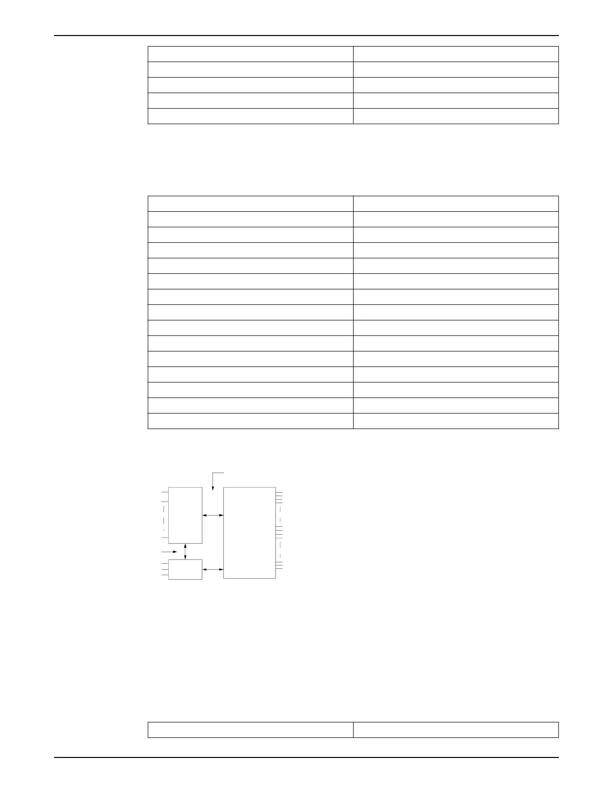
1. +24 V
2. 18
3. 37
4. Functional isolation
5. RS485
6. Control
7. PELV isolation
8. High voltage
9. Mains
10.Motor
11.DC-Bus
Figure 99: PELV isolation
Pulse inputs
Programmable pulse inputs 2
9 Technical Specification
Aquavar
®
Intelligent Pump Controller - 150 HP to 600 HP INSTRUCTION MANUAL 155