A
1
2
3
4
5
6
7
8
9
10
BCDEFGH I JK
L MN
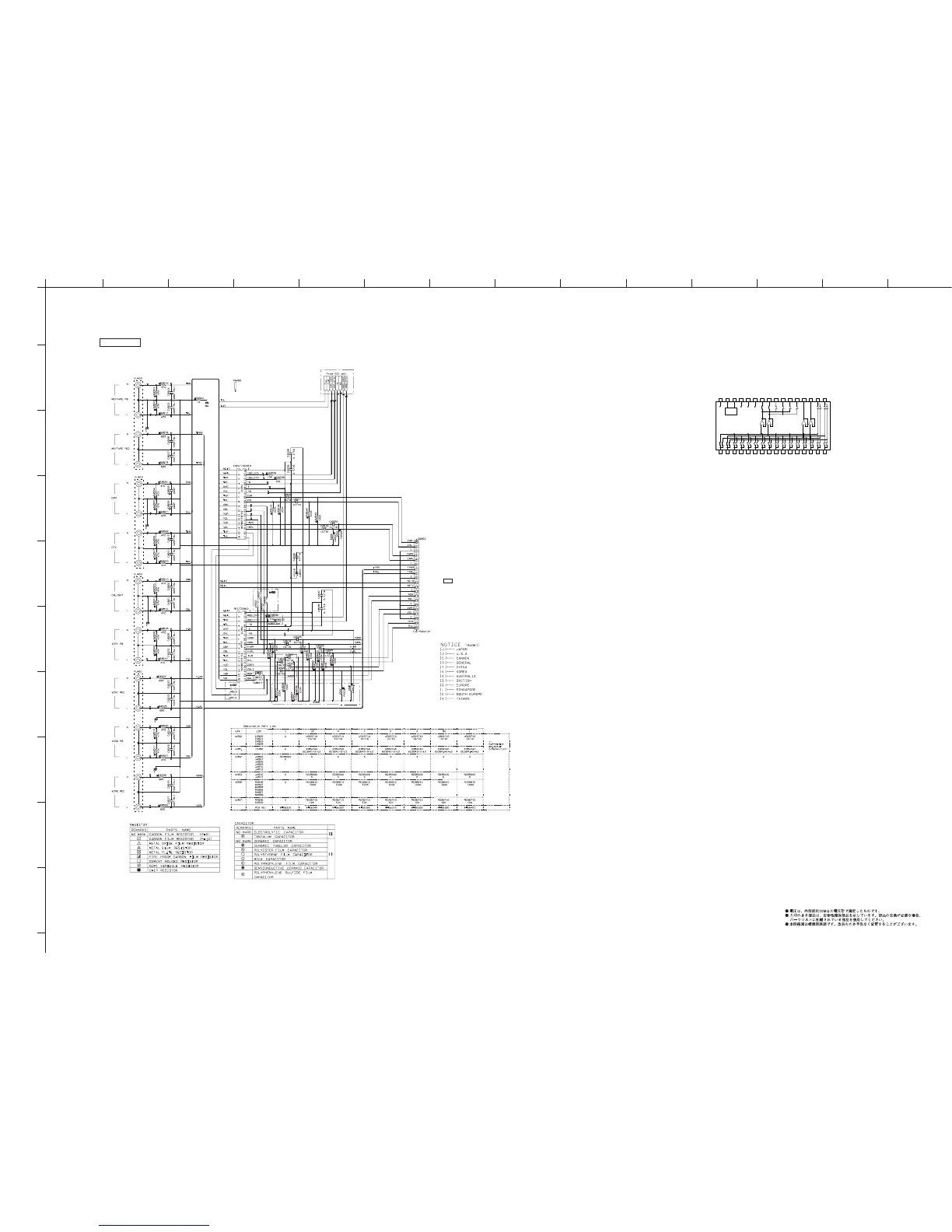
RX-V1700/DSP-AX1700
107
★ All voltages are measured with a 10MΩ/V DC electronic voltmeter.
★ Components having special characteristics are marked s and must be replaced
with parts having specifications equal to those originally installed.
★ Schematic diagram is subject to change without notice.
FUNCTION 2/4
0
0
0
0
0
0
0-6.1
0
6.1
0
0
0
0
0
0
0
0
0
0
0
0
0
0
0
0
0
0
0
0
0
0
0
0
0
-6.1
0
6.1
0
0
0
0
0
0
0
0
0
0
0
0
0
0
0
0
0
0
0
0
0
0
0
0
0
INPUT/ZONE3
SELECTOR
REC/ZONE2
SELECTOR
FUNCTION (1)
F-SW1
F-SW1: INPUT FUNCTION 1
F-SW2: INPUT FUNCTION 2
*
32 31 30 29 28 27 26 25 24 23 22 21 20 19 18 17
1 2 3 4 5 6 7 8 9 10 11 12 13 14 15 16
IC450, 451: BD3841FS
Function switch
DGND
F-SW2
CL
DA
VEE
BIAS
VCC
RECA1
RECA2
RECB1
RECB2
RECC1
RECC2
OUT1
OUT2
INI1
INI2
INA1
INA2
INB1
INB2
INC1
INC2
IND1
IND2
INE1
INE2
INF1
INF2
ING1
ING2
INH1
INH2
LOGIC
+
–
+
–
+
–
+
–
to FL (4)_CB963
Page 118
J2
 Loading...