PM5D/PM5D-RH V2 / DSP5D Owner’s Manual Reference section 385
Information shown
in the display
Function
menu
Global
functions
Output
functions
Input
functions
Appendices
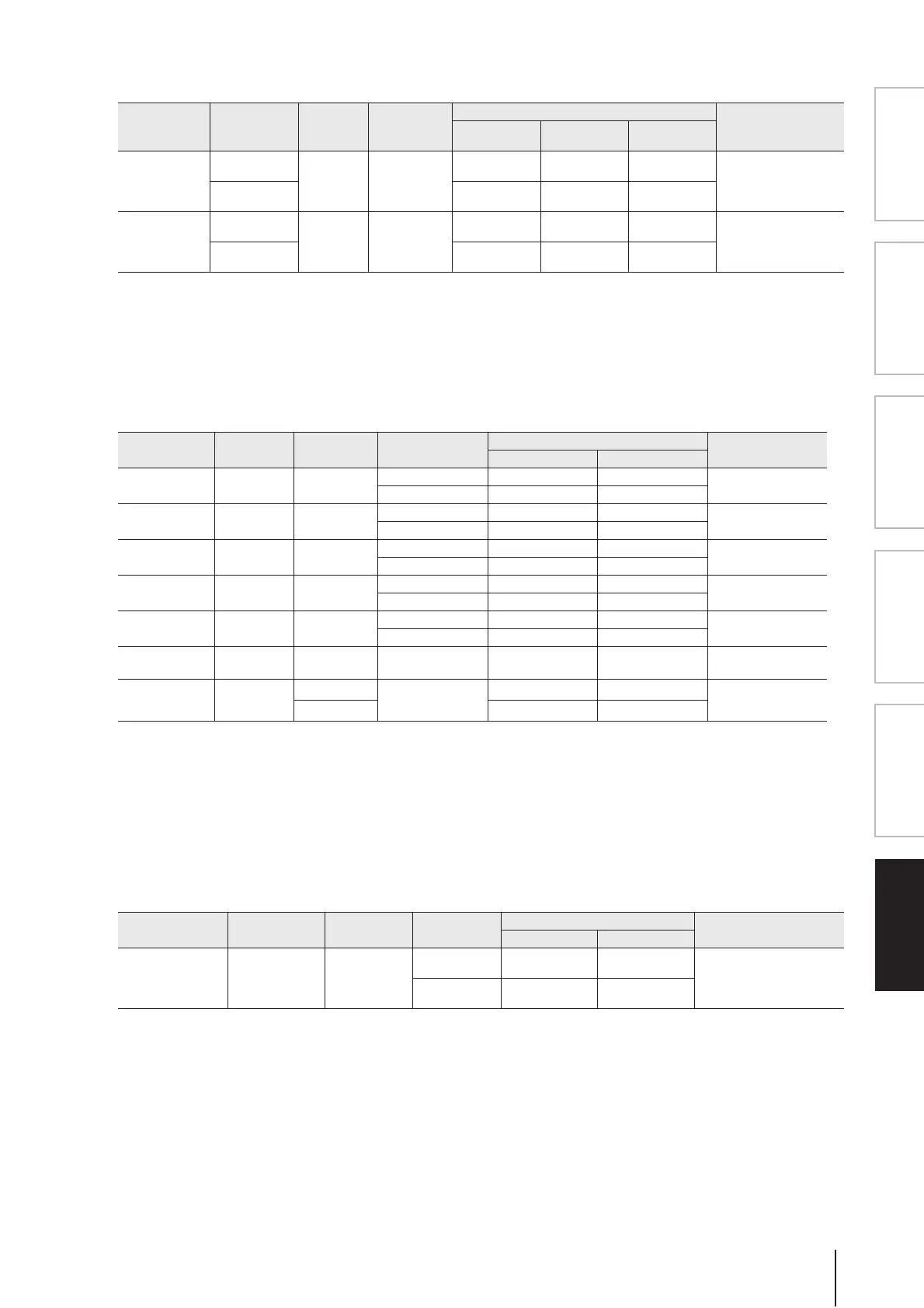
❏ Analog Input Characteristics (DSP5D)
*1. Sensitivity is the lowest level that will produce an output of +4 dBu (1.23 V) or the nominal output level when the unit is set to maximum gain. (all faders
and level controls are maximum position.)
*2. XLR-3-31 type connectors are balanced. (1=GND, 2=HOT, 3=COLD)
* In these specifications, 0 dBu = 0.775 Vrms.
* All input AD converters are 24bit linear, 128 times (@48 kHz) oversampling.
* +48V DC (phantom power) is supplied to INPUT (1-48) XLR type connectors via one master and each individual software switches.
❏ Analog Output Characteristics (PM5D, PM5D-RH)
*1. XLR-3-32 type connectors are balanced. (1=GND, 2=HOT, 3=COLD)
*2. Phone jacks are balanced. (Tip=HOT, Ring=COLD, Sleeve=GND)
*3. PHONES stereo phone jacks are unbalanced. (Tip=LEFT, Ring=RIGHT, Sleeve=GND)
*4. There are switches inside the body to preset the maximum output level.
*5. INSERT OUTs are only provided for PM5D.
*6. The position of the level control is 10 dB lowered from Max.
* In these specifications, 0 dBu = 0.775 Vrms.
* All output DA converters are 24bit, 128 times (@48 kHz) oversampling.
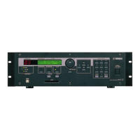
❏ Analog Output Characteristics (DSP5D)
*1. XLR-3-32 type connectors are balanced. (1=GND, 2=HOT, 3=COLD)
*2. There are switches inside the body to preset the maximum output level.
* In these specifications, 0 dBu = 0.775 Vrms.
* All output DA converters are 24bit, 128 times (@48 kHz) oversampling.
Input Terminals GAIN
Actual Load
Impedance
For Use With
Nominal
Input Level
Connector
Sensitivity
*1
Nominal
Max. before
clip
INPUT 1-48
–62 dB
3kΩ
50-600Ω Mics
&
600Ω Lines
–82 dBu
(61.6 µV)
–62 dBu
(0.616 mV)
–42 dBu
(6.16 mV)
XLR-3-31 type
(Balanced)
*2
+10 dB
–10 dBu
(245 mV)
+10 dBu
(2.45 V)
+30 dBu
(24.5 V)
ST IN 1-4 [L,R]
–62 dB
3kΩ
50-600Ω Mics
&
600Ω Lines
–82 dBu
(61.6 µV)
–62 dBu
(0.616 mV)
–42 dBu
(6.16 mV)
XLR-3-31 type
(Balanced)
*2
+10 dB
–10 dBu
(245 mV)
+10 dBu
(2.45V)
+30 dBu
(24.5 V)
Output
Terminals
Actual Source
Impedance
For Use With
Nominal
GAIN SW
*4
Output Level
Connector
Nominal Max. Before Clip
STEREO A,B [L,R] 150Ω 600Ω Lines
+24 dB (default) +4 dBu (1.23 V) +24 dBu (12.28 V)
XLR-3-32 Type
(Balanced)
*1
+18 dB –2 dBu (616 mV) +18 dBu (6.16 V)
MONITOR OUT
[L,R,C]
150Ω 600Ω Lines
+24 dB (default) +4 dBu (1.23 V) +24 dBu (12.28 V)
XLR-3-32 Type
(Balanced)
*1
+18 dB –2 dBu (616 mV) +18 dBu (6.16 V)
CUE OUT [L,R] 150Ω 600Ω Lines
+24 dB (default) +4 dBu (1.23 V) +24 dBu (12.28 V)
XLR-3-32 Type
(Balanced)
*1
+18 dB –2 dBu (616 mV) +18 dBu (6.16 V)
MATRIX OUT 1-8 150Ω 600Ω Lines
+24 dB (default) +4 dBu (1.23 V) +24 dBu (12.28 V)
XLR-3-32 Type
(Balanced)
*1
+18 dB –2 dBu (616 mV) +18 dBu (6.16 V)
MIX OUT 1-24 150Ω 600Ω Lines
+24 dB (default) +4 dBu (1.23 V) +24 dBu (12.28 V)
XLR-3-32 Type
(Balanced)
*1
+18 dB –2 dBu (616 mV) +18 dBu (6.16 V)
INSERT OUT 1-48 150Ω 10kΩ Lines — +4 dBu (1.23 V) +24 dBu (12.28 V)
Phone Jack (TRS)
(Balanced)
*2 *5
PHONES (x 2) 15Ω
8Ω Phones
—
75 mW
*6
150 mW
Stereo Phone Jack
(TRS) (Unbalanced)
*3
40Ω Phones
65 mW
*6
150 mW
Output Terminals
Actual Source
Impedance
For Use With
Nominal
GAIN SW
*2
Output Level
Connector
Nominal Max. before clip
OMNI OUT 1-24 150Ω 600Ω Lines
+24 dB
(default)
+4 dBu
(1.23 V)
+24 dBu
(12.28 V)
XLR-3-32 type (Balanced)
*1
+18 dB
–2 dBu
(616 mV)
+18 dBu
(6.16 V)