ENGINE
5-58
BY Service Manual
Camshaft and Timing Gear Train
Figure 5-100
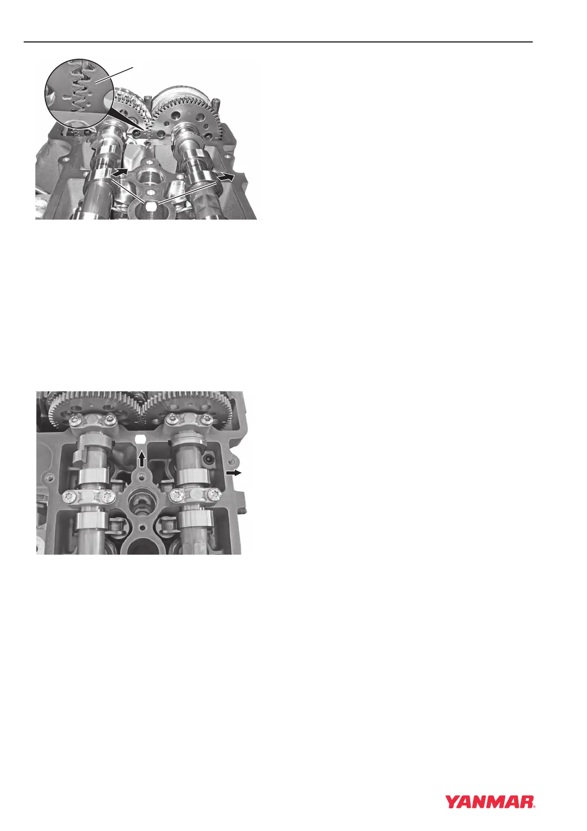
3. Install camshafts. Ensure the timing marks
(Figure 5-100, (1)) on the gears align as
shown.
When the timing marks are aligned, the lobes
(Figure 5-100, (2)) for cylinder No. 1 will face the
exhaust side of the engine.
Note: The valves will hold the camshafts above
the bearing seats until all bolts are
tightened.
Figure 5-101
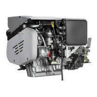
Note: Bearing caps are numbered beginning at
the front (Figure 5-101, (1)) of the
engine. The numbered markings of all
caps should face the exhaust side
(Figure 5-101, (2)).
4. Install bearing caps in their proper locations.
• Intake camshaft bearing caps are marked
E1 - E7.
• Exhaust camshaft bearing caps are marked
A1 - A7
5. Lightly oil the threads of all bolts and install
finger-tight.
6. Tighten all bearing caps evenly in 1/2-turn
increments, starting at the center and working
toward each end, until all bearing caps are
seated.
7. Tighten all bearing cap bolts to 10 N·m
(89 in.-lb).
8. Install chain on sprocket and install sprocket on
intake camshaft. Tighten bolts until snug.
9. Install guide rails.
10. Apply medium strength thread lock and sealer
to the threads of the guide rail bearing pins.
Install and tighten to 20 N·m (177 in.-lb).
11. Adjust camshaft timing. See Adjusting
Camshaft Timing on page 5-49.
12. Remove flywheel holding tool and install
protective cap.
13. Remove chain tensioner locks.
14. Install cylinder head cover. See Remove and
Install Cylinder Head Cover on page 5-20.
0003778
(
1
)
(
2
)
0003779
(
2
)
(
1
)
E2
A2
E2
E1
E1
A2
A1
A1