FUEL SYSTEM
6-10
BY Service Manual
Fuel Flow Diagram
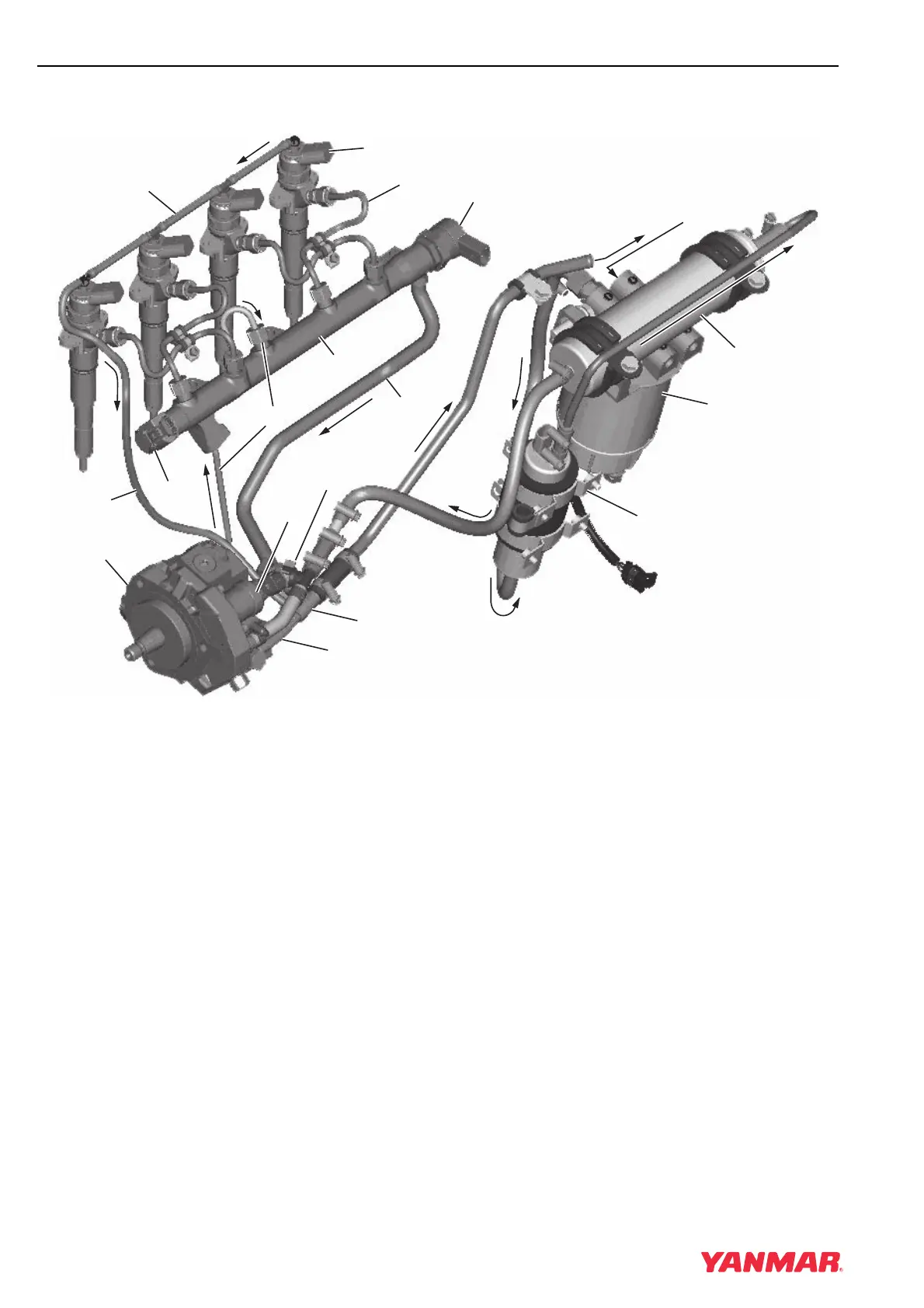
FUEL FLOW DIAGRAM
Figure 6-3
Note: 4BY system shown. 6BY is similar.
1 – Fuel Inlet from Tank
2 – Fuel Filter / Water Separator (10 micron)
3 – Fuel Feed Pump
4 – Fuel Fine Filter (3 micron)
5 – Inlet Fuel Temperature Sensor
6 – High-Pressure Fuel Pump
7 – High-Pressure Fuel Supply Line
8 – High-Pressure Fuel Rail
9 – Fuel Injection Line
10 – Fuel Injector
11 – Fuel Injector Return Hose
12 – Common Rail Return Line
13 – Return Fuel Tee
14 – High-Pressure Pump Return Hose
15 – Return Fuel to Fuel Tank
16 – Fuel Pressure Sensor
17 – Fuel Pressure Regulator (ECU-Controlled)
18 – Fuel Measuring Unit (ECU-Controlled)
0003634
(3)
(2)
(14)
(13)
(18)
(5)
(7)
(16)
(11)
(10)
(9)
(6)
(4)
(15)
(1)
(11)
(17)
(12)
(8)