ENGINE
5-72
BY Service Manual
Exhaust Manifold
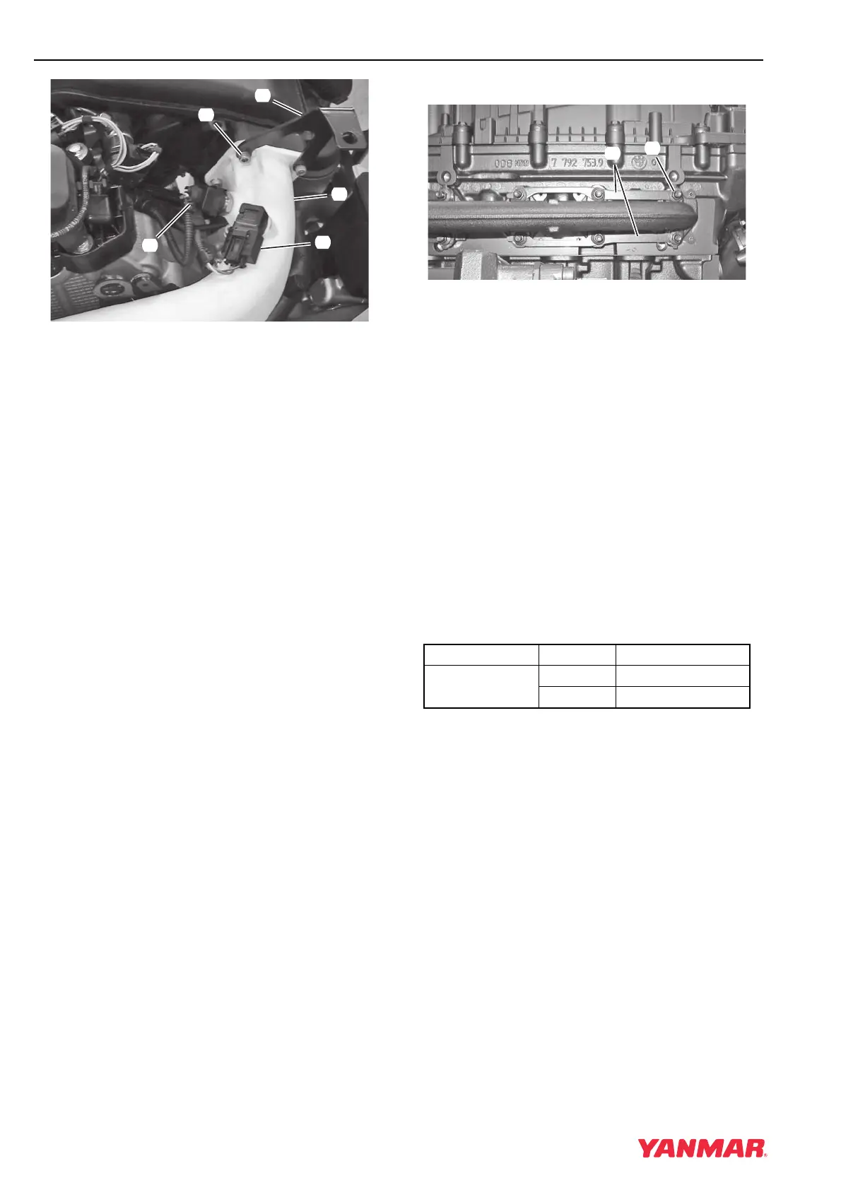
Figure 5-128
8. Ensure seal in charge air pipe is not damaged
and is in place. Connect charge air pipe
(Figure 5-128, (4)) and bracket
(Figure 5-128, (5)). Install four screws
(Figure 5-128, (3)) and tighten to 9.5 N·m
(84 in.-lb)
9. Connect electrical connectors to charge air
pressure sensor (Figure 5-128, (1)) and charge
air temperature sensor (Figure 5-128, (2)).
10. Secure injector harness to intake manifold and
connect to fuel injectors.
EXHAUST MANIFOLD
Remove
1. Remove heat exchanger. See Remove and
Install Heat Exchanger on page 7-16.
2. Remove turbocharger. See Turbocharger
Removal on page 9-9.
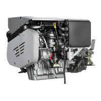
6BY Engine Shown
Figure 5-129
3. Remove nuts (Figure 5-129, (1)).
4. 6BY Engines: Remove plates
(Figure 5-129, (2)).
5. Remove manifold from engine.
Install
1. Clean mounting surfaces of all gasket material.
2. Apply a light coating of copper anti-seize to
mounting studs.
3. Install new gaskets.
4. Install manifold with new nuts.
6BY Engines: Install plates (Figure 5-129, (2)).
Tighten nuts to specification.
Specifications
5. Install turbocharger. See Turbocharger
Installation on page 9-10.
6. Install heat exchanger. See Remove and Install
Heat Exchanger on page 7-16.
0003781
(
1
)
(
4
)
(
5
)
(
3
)
(
2
)
Item Engine Torque
Exhaust Manifold
Torque
4BY 19 N·m (168 in.-lb)
6BY 13 N·m (115 in.-lb)
0003798
(
2
)
(
1
)