ENGINE
5-22
BY Service Manual
Cylinder Head
Figure 5-6
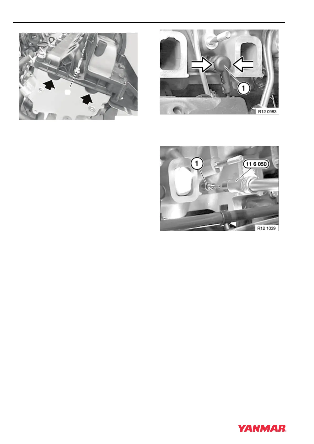
Note: Double-ended bolts (Figure 5-6, (1)) are
used on the inner row only.
4. Install cylinder head cover. Tighten bolts in two
stages to 9.5 N·m (84 in.-lb). Tighten inner row
(Figure 5-6, (1)) working evenly from the center
towards each end. Tighten outer bolts evenly
and diagonally.
5. Connect breather hose to vacuum chamber.
6. Install rubber gasket and oil filler cap.
7. Install fuel injectors and connect high-pressure
fuel lines. See Installation of Fuel Injector on
page 6-16.
8. Install intake manifold. See Intake Manifold on
page 5-70.
9. Connect electrical connectors to the fuel
injectors, camshaft sensor, intake air pressure
sensor, and intake air temperature sensor.
10. Install engine cover.
Remove and Install Glow Plugs
1. Disconnect battery negative (-) terminal.
2. Remove intake manifold. See Intake Manifold
on page 5-70.
Figure 5-7
3. Release locks and remove connector
(Figure 5-7, (1)) from glow plug.
Figure 5-8
4. Use special tool OEM No. 11 6 050 to remove
glow plug (Figure 5-8, (1)) from cylinder head.
Note: If glow plug failure has occurred, it is
essential to check condition of fuses.
5. Test and replace glow plug as necessary.
6. Install glow plug using special tool OEM No.
11 6 050. Tighten to 17.5 N·m (154 in.-lb).
7. Install intake manifold. See Intake Manifold on
page 5-70.
8. Check and delete any trouble codes that are
registered in the ECU after the work has been
completed. See After Troubleshooting or Repair
on page 13-13.
R11 0854 A
(
1
)