ENGINE
BY Service Manual
5-37
Pistons and Cylinders
IMPORTANT
Do not allow the connecting rod to bump the
crankshaft journal during piston removal.
Damage to the bearing journal may result.
10. Push the piston and connecting rod out of the
cylinder. Use a wooden dowel against the
connecting rod if necessary.
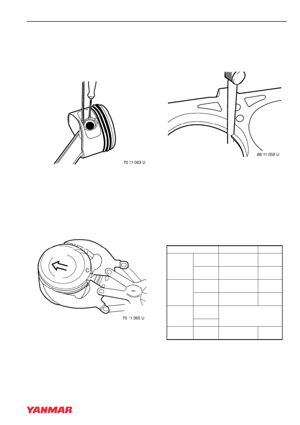
Figure 5-47
11. Remove the wrist pin retaining rings
(Figure 5-47).
IMPORTANT
Pistons and wrist pins are matched. NEVER
mix parts.
12. Push out the wrist pin. Keep piston and
matched wrist pin together.
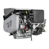
Figure 5-48
13. Use a piston ring expander (Figure 5-48, (1)) to
remove the piston rings, taking care not to
scratch the surface of the piston.
Inspection of Pistons and Piston
Rings
Figure 5-49
Note: Measure cylinder bore to ensure it is
within specifications before measuring
piston ring end gap. See Inspection of
Cylinder Block on page 5-66.
1. Insert each piston ring, one at a time, into the
cylinder. Use a piston with the piston rings
removed to slide the ring squarely into the
cylinder bore. Measure the end gap of each
piston ring (Figure 5-49).
Specifications
Inspection Item Standard Limit
Top Piston
Ring
Side
Clearance
0.12 - 0.16 mm
(0.005 - 0.006 in.)
-
End Gap
0.20 - 0.35 mm
(0.008 - 0.014 in.)
-
Second
Piston
Ring
Side
Clearance
0.07 - 0.11 mm
(0.003 - 0.004 in.)
-
End Gap
0.30 - 0.45 mm
(0.012 - 0.018 in.)
-
Oil Ring
Side
Clearance
Cannot be measured
End Gap
Piston-to-
Cylinder
Clearance
0.15 mm
(0.006 in.)