ENGINE
BY Service Manual
5-71
Intake Manifold
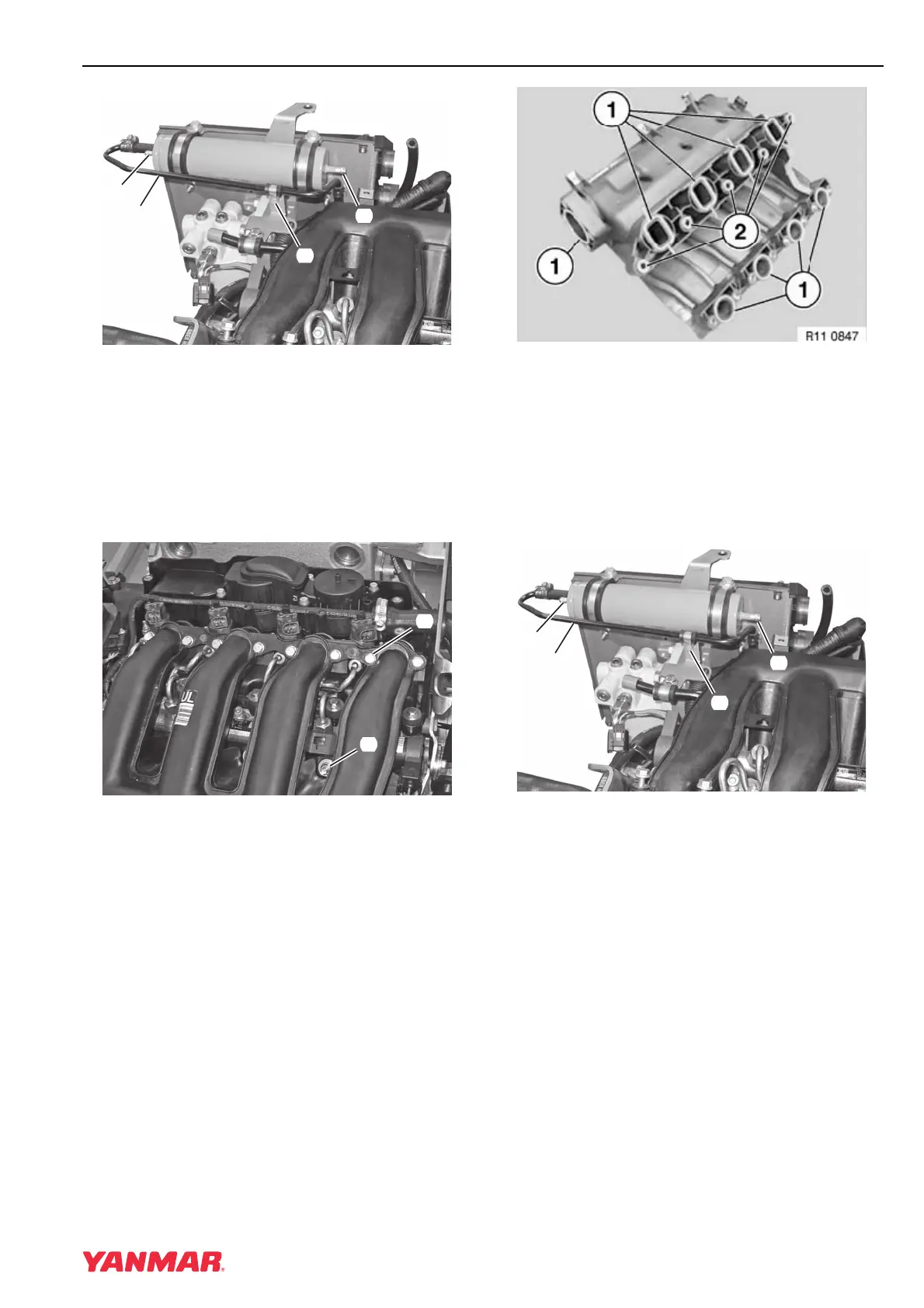
Figure 5-124
5. Disconnect inlet (Figure 5-124, (1)) and outlet
(Figure 5-124, (2)) hoses from the fuel fine
filter.
6. Remove clamp bolt (Figure 5-124, (3)) to allow
fuel inlet line (Figure 5-124, (4)) to move.
7. Remove fuel fine filter from electrical bracket.
Figure 5-125
8. Remove bolts (Figure 5-125, (1)).
9. Remove nuts (Figure 5-125, (2)).
10. Remove intake manifold.
Installation
1. Clean all sealing surfaces.
Figure 5-126
2. Install new sealing rings (Figure 5-126, (1)).
3. Check condition of rubber mounts
(Figure 5-126, (2)) and replace if damaged.
4. Install manifold on engine.
5. Install bolts and nuts. Tighten to 15 N·m
(133 in.-lb).
Figure 5-127
6. Install fuel fine filter. Connect inlet
(Figure 5-127, (1)) and outlet
(Figure 5-127, (2)) hoses.
7. Secure inlet line clamp (Figure 5-127, (3)).
0003783
(
1
)
(
2
)
(
4
)
(
3
)
0003782
(
1
)
(
2
)
0003783
(
1
)
(
2
)
(
4
)
(
3
)