ENGINE
5-24
BY Service Manual
Cylinder Head
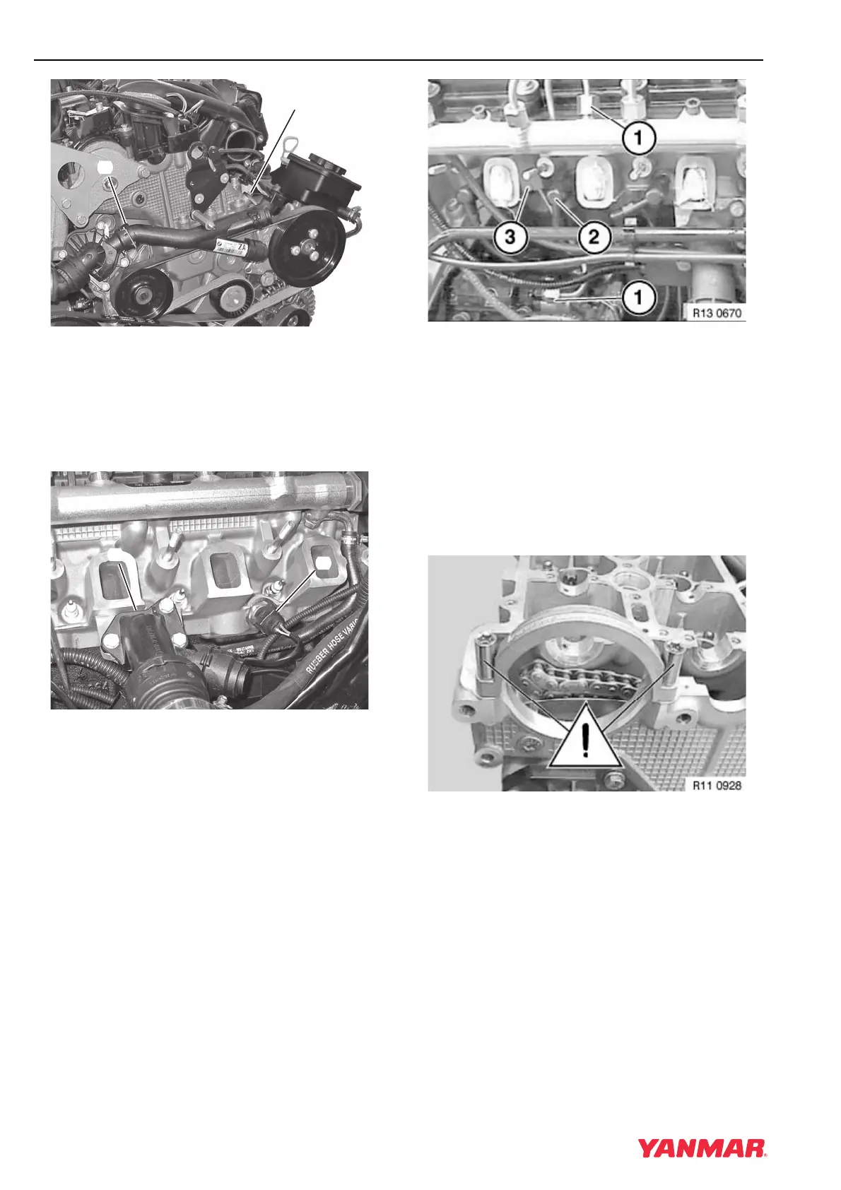
Figure 5-11
12. Remove screw (Figure 5-11, (1)) that retains oil
cooler return pipe to cylinder head.
13. Release locks and disconnect coolant return
pipe (Figure 5-11, (2)). See Disconnect and
Connect Quick-Connect Fittings on page 7-13.
Figure 5-12
14. Remove three bolts and remove coolant branch
fitting (Figure 5-12, (1)).
15. Disconnect electrical connector from coolant
temperature sensor (Figure 5-12, (2)).
Figure 5-13
16. Remove high-pressure fuel rail. See Removing
and Installing Fuel Rail on page 6-27.
17. Remove pump-to-fuel rail high-pressure line
(Figure 5-13, (1)).
Note: 4BY Engines: Make note of position of
the rubber mount (Figure 5-13, (3)) for
reassembly.
18. Remove glow plugs (Figure 5-13, (2)). See
Remove and Install Glow Plugs on page 5-22.
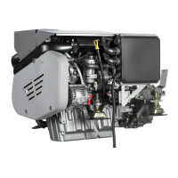
Figure 5-14
IMPORTANT
NEVER remove bolts retaining loop casting
(Figure 5-14).
0003766
(
1
)
(
2
)
0003767
(
1
)
(
2
)