2.7 Communications with a Mitsubishi PLC (QnA-compatible 3E Frame Protocol)
Using the MSG-SNDE Function with the MP3000 as the Master
2-148
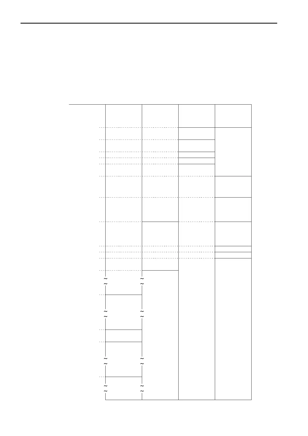
The following map, based on bit and word device conversion tables, shows how M registers in the
MP3000 correspond to devices in the Mitsubishi Q/QnA-series PLCs. All devices in a Mitsubishi Q/QnA-
series PLC are assigned to hold registers, input registers, input relays, and coils so that the MP3000 can
read and write to them by using MEMOBUS commands as an interface. Data read from a device in the
Mitsubishi Q/QnA-series PLC is stored in the corresponding M register in the map. The data that is writ-
ten to the device in the Mitsubishi Q/QnA-series PLC is sent by forming a message that contains the con-
tents of the corresponding M register in the map.
00000
F•••••••••••0F•••••••••••0F•••••••••••0F•••••••••••0
00512
01024
01536
02048
02560
02688
02816
03072
12288
20480
22528
00640
00768
00832
00896
55296
00511
00767
00639
00831
00895
01023
01535
02047
02559
02687
02815
02071
12287
20479
22527
55295
65534
M Register
Data Address
Hold Registers Input Registers Input Relays
Input relays: X
Timer contacts: TS
Timer coils: TC
Counter contacts: CS
Counter coils: CC
Internal relays: M
Timer registers: TN
Latch relays: L
Data registers: D
Step relays: S
Counter registers:
CN
File registers: R
Special registers:
SD
Link registers: W
Link relays: B
Annunciators: F
Link special relays: SM
Output relays: Y
Coils

 Loading...


