5 Main Circuit and Motor Wiring
YASKAWA America, Inc. PL.GA500.01 YASKAWA AC Drive - V1000 to GA500 Transition Guide 13
Wire Termination Differences V1000 to GA500
If crimp terminal ends/ring lugs are present on the V1000, they must be removed and the wire stripped to bare wire for
installation to the GA500. Refer to the GA500 Installation & Primary Operation Manual No. TOEPC71061752, for more
information on wire termination.
Main Circuit and Motor Terminal Layout Comparison
Terminal location and appearance differs slightly between V1000 and GA500. Use this section to understand differences
to prepare for wiring the GA500.
•Refer to Figure 2 for V1000 Main Circuit and Motor Circuit Terminal Layout by Model
•Refer to Figure 3 for GA500 Main Circuit and Motor Circuit Terminal Layout by Model
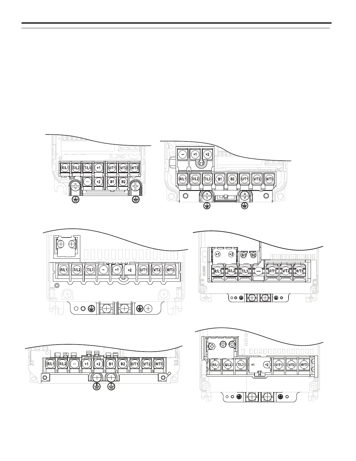
Figure 2
Figure 2 V1000 Main Circuit and Motor Circuit Terminal Layout by Model
Models: CIMR-V
BA0001, 0002, 0003
CIMR-V2A0001, 0002, 0004, 0006
Models: CIMR-V
BA0006, 0010, 0012
CIMR-V2A0010, 0012, 0020
CIMR-V4A0001, 0002, 0004, 0005
0007, 0009, 0011
Models: CIMR-V
2A0030, 0040
CIMR-V4A0018, 0023
Model: CIMR-V
2A0069
Model: CIMR-V
BA0018
Models: CIMR-V
2A0056
CIMR-V4A0031, 0038

 Loading...


