6 Control Circuit Wiring
YASKAWA America, Inc. PL.GA500.01 YASKAWA AC Drive - V1000 to GA500 Transition Guide 19
6 Control Circuit Wiring
Use this section to understand differences between the V1000 and GA500 control circuit wiring to transfer control circuit
wiring to the GA500. Refer to the GA500 Installation & Primary Operation Manual or Technical Reference for more
details and precautions when wiring the GA500 control circuit terminals.
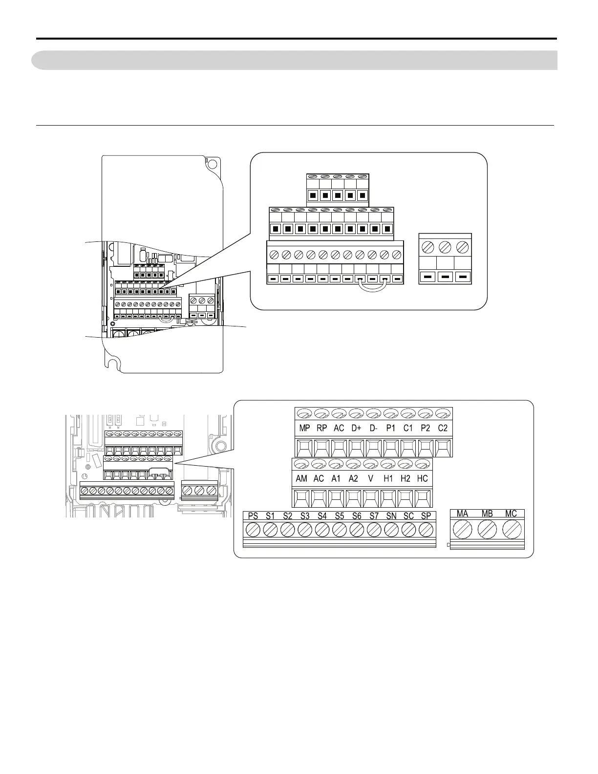
Control Circuit Terminal Layout
Figure 4
Figure 4 V1000 Control Circuit Terminals
Figure 5
Figure 5 GA500 Control Circuit Terminals
S1 S2 S3 S4 S5 S6 S7 HC SC H1 RP
R+ R– S+ S– IG
P1 P2 PC A1 A2 +V AC AM AC MP
AMBMCM
S1 S2 S3 S4 S5 S6 S7 HC SC H1 RP
R+ R- S+ S- IG
P1 P2 PC A1 A2 +V AC AM AC MP
AMBMCM

 Loading...


