6 Control Circuit Wiring
26 YASKAWA America, Inc. PL.GA500.01 YASKAWA AC Drive - V1000 to GA500 Transition Guide
Control Circuit Switches and Jumpers
Use this section to make any needed changes to the GA500 control circuit switches or jumpers.
V1000 Switches and Jumpers
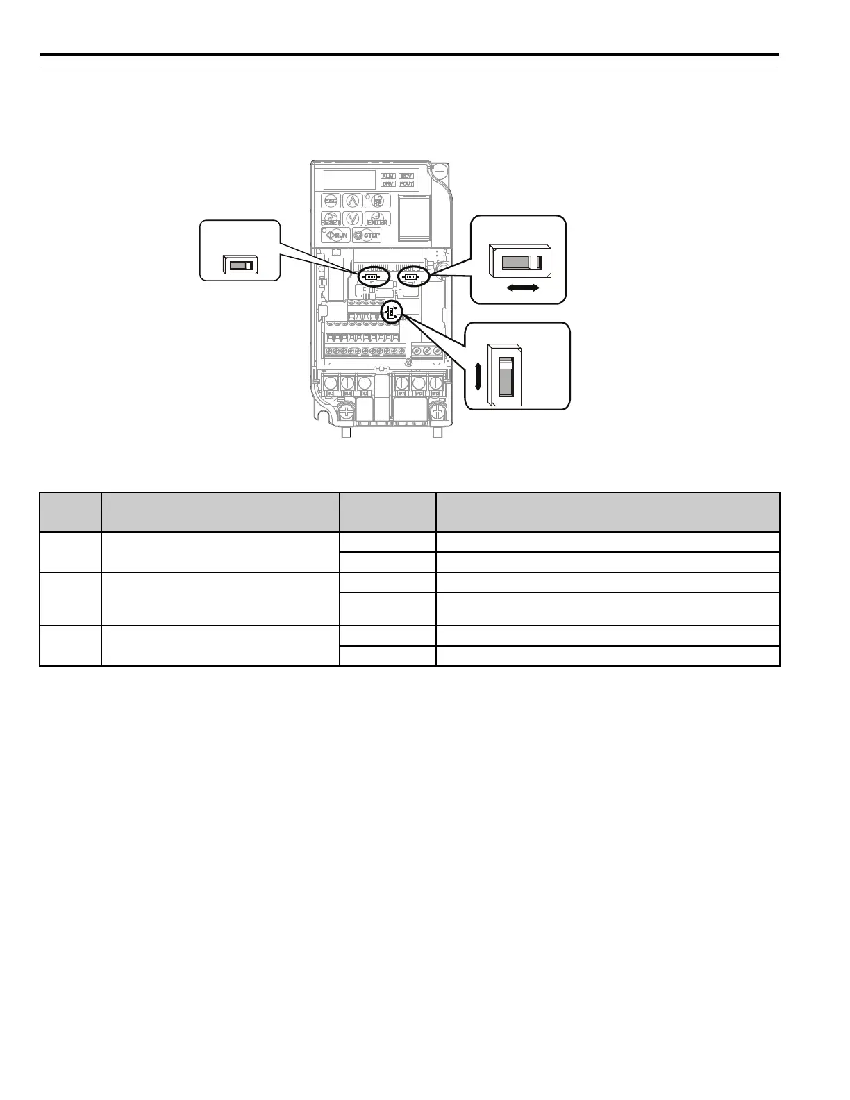
Figure 8
Figure 8 V1000 DIP Switches
Table 12 V1000 DIP Switch Settings
DIP
Switch
Switch Function Setting Value DIP Switch Setting Description
S1
Analog input signal selection for voltage or
current for terminal A2
V (left position) Voltage input (0 to 10 V)
I (right position) Current input (4 to 20 mA or 0 to 20 mA): default setting
S2
MEMOBUS/Modbus termination resistor
switch setting for the RS-485, RS-422
communication terminals R-, R+, S-S+
ON Internal termination resistor ON
OFF
Internal termination resistor OFF (no termination resistor): default
setting
S3
Sinking/sourcing mode switch for digital
input terminals S1~S7
SINK Sinking Mode (0 V common): default setting
SOURCE Sourcing Mode (+24 V common)
SINK
SOURCE
VI
(in the ON position)
OFF ON
DIP Switch S1
DIP Switch S3
DIP Switch S2

 Loading...


