6 Control Circuit Wiring
20 YASKAWA America, Inc. PL.GA500.01 YASKAWA AC Drive - V1000 to GA500 Transition Guide
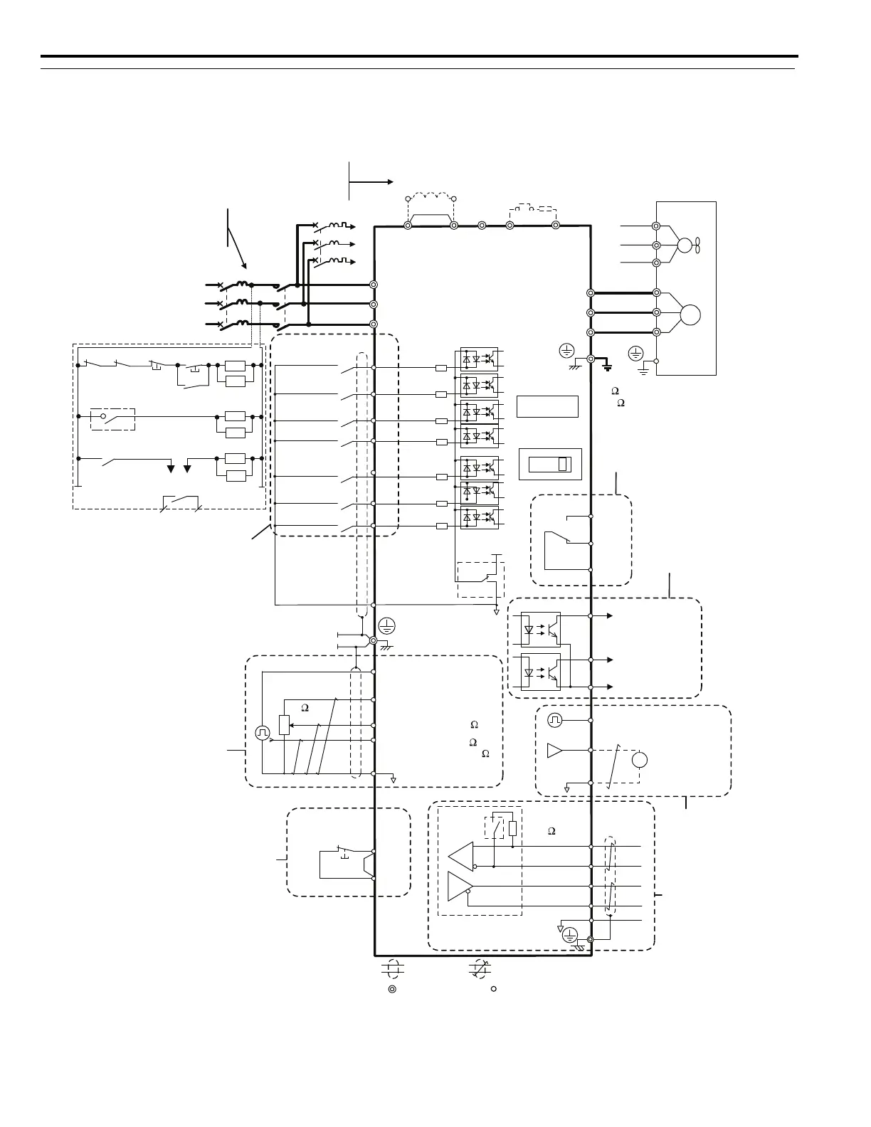
Control Circuit Connection Diagrams
Refer to the GA500 Installation & Primary Operation Manual or Technical Reference for complete details on the GA500
control circuit.
Figure 6
Figure 6 V1000 Connection Diagram
+
-
1 MCCB
MC
2 MCCB
r1
s1
t1
<3>
R/L1
S/L2
T/L3
For single-phase
200 V power supply
use R/L1 and S/L2.
Three phase
power supply
for 200 V / 400 V
Terminals +1, +2, − , B1, and B2
are for connecting options.
Never connect power supply
lines to these terminals.
Digital inputs
(default setting)
Forward run/stop
Reverse run/stop
External fault
Fault reset
Multi-step
speed 2
Jog reference
S1
S2
S3
S4
S5
S6
S7
Multi-step
speed 1
main/aux switch
<4>
DC link choke
(option)
V1000
Thermal relay
(option)
Main circuit
Control circuit
R/L1
S/L2
T/L3
<1>
<2>
-
B1+1+2 B2
Jumper
Motor
Cooling fan
Braking resistor
(option)
U/T1
V/T2
W/T3
M
M
r1
s1
t1
FU
FV
FW
U
V
W
Ground
10
or less (400 V class)
100
or less (200 V class)
Digital output
250 Vac, 10 mA to 1 A
30 Vdc, 10 mA to 1 A
(default setting)
Option card
connector
Fault
MA
P1
MB
MC
P2
MP
PC
During Run
(photocoupler 1)
Frequency agree
(photocoupler 2)
Photocoupler
output common
Digital output
5 to 48 Vdc
2 to 50 mA
(default setting)
Pulse train output
0 to +10 Vdc
(2 mA)
Comm.
connector
AM
AC
AM
0 to 32 kHz
Analog monitor
output
Termination
resistor
Monitor
output
<6>
IG
R
+
R
-
S
+
S
-
MEMOBUS/
Modbus comm.
RS-485/422
120
, 1/2 W
Cable shield ground
DIP
switch
S2
main circuit terminal
shielded line
twisted-pair shielded line
control terminal
Safe Disable
Input
Safety switch
HC
H1
Jumper
<7>
Main speed
frequency
reference.
Multi-function
programmable
RP
+V
A1
A2
AC
2 k
Pulse train input
(max. 32 kHz)
0 to +10 V (20 k
)
Setting power supply
+10.5 max. 20 mA
0 to +10 V (20 k
)
(0)4 to 20 mA (250
)
DIP
switch S3
Shield ground
terminal
0V
SC
Sink
Source
<5>
24 V
+
24 V 8 mA
Wiring sequence should shut off
power to the drive when a fault
<8>
output is triggered.
TRX
ON
OFF
THRX
SA
1
2
TRX
MC
MC
MB
TRX
Fault relay contact
Braking resistor unit
Thermal relay trip contact
MC
SA
SA
THRX
VI
DIP switch S1

 Loading...


