5-58
Continued
—For undertorque detection during accel or decel, set to " 3 " or " 4 ".
—For continuous operation after undertorque detection, set to " 1 " or " 3 ". During detection, the Digital Operator
displays and “ UL3 ” alarm (blinking).
—To stop the drive at an undertorque detection fault, set to " 2 " or " 4 ". At detection, the Digital Operator displays an
" UL3 " fault.
—To output an undertorque detection signal, set output terminal function selection (n057, n058 or n059 ) to
" 8 " or " 9 ".
B. n118 : Undertorque Detection Level
Factory setting: 10 %
Range: 0 to 200 %
This is the reference point for determining that an undertorque condition exists. Set as a percent of Drive rated
current or as a percent of motor rated torque.
C. n119 : Undertorque Detection Time
Factory setting: 0.1 sec.
Range: 0.1 to 10.0 seconds
Determines how long an undertorque condition must exist before another event will occur, e.g. coast to stop,
multi-function output change of state, or UL3 warning or fault display.
D. n057 : Multi-function Output 1 Data 6 or 7 :Overtorque
(terminals MA, MB & MC) Detection
n058 : Multi-function Output 2 Data 8 or 9 : Undertorque
(terminals P1 & PC) Detection
n059 : Multi-function Output 3
(terminals P2 & PC)
A Form-C contact, or an open collector output, can be programmed to change states during an
overtorque/undertorque detection condition.
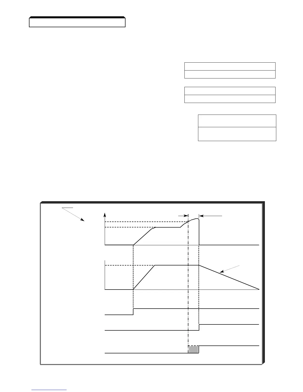
EXAMPLE OF OVERTORQUE DETECTION
n096 setting: 2 — Overtorque enabled, only at set frequency, coast to stop
n057 setting: 6 — Output contact programmed for overtorque detection
n096 setting: 110 %— Level at which overtorque is sensed
n099 setting: 1.0 s— Time delay before overtorque event occurs
Detection level
(n098 )
Detection
110% time
OUTPUT 100% (n099)
CURRENT/
TORQUE
0
100%
Coast
MOTOR
stop
SPEED
0
RUN
SIGNAL
FAULT
SIGNAL
CONTACT OUTPUT
(OVERTORQUE
DETECTION)
TERM. MA & MC)
Overtorque Detection Timing Diagram
5.34 UNDERTORQUE DETECTION