6-3
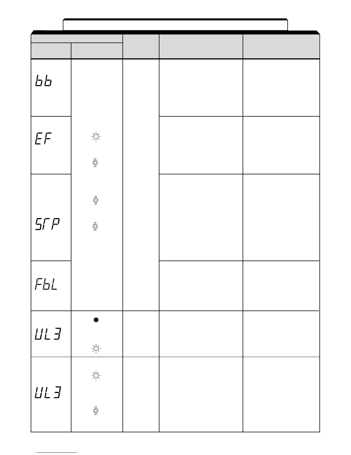
Alarm Display
Digital RUN (Green)
Drive
Explanation
Causes and
Operator ALARM (Red)
Status Corrective Actions
BB (External baseblock) Check the external circuit
Baseblock command at (sequence).
multi-function terminal is
active, the drive output
Blinking is shut OFF (motor coasting).
Temporary condition is
cleared when input command
is removed.
EF (Simultaneous FWD/ Check the external circuit
REV run commands) (sequence).
When FWD and REV
run commands are
Blinking simultaneously input
for over 500ms, the
drive stops according
Warning
to parameter n005.
only. STP (Operator function Open FWD/REV
Fault stop) is pressed during command of control
contacts running by the control circuit circuit terminals.
do not terminals FWD / REV
change command.
state. The drive stops according
to parameter n005.
STP (Emergency stop)
Blinking Drive receives emergency
stop alarm signal. Check the external circuit
Drive stops according (sequence).
to parameter n005.
FBL (PID feedback loss Check the mechanical
detection) system and correct the
PID feedback value drops cause, or increase the
below the detection level. value of n137.
Blinking
When PID feedback loss is
detected, the Drive operates
according to the n136 setting.
Protective When under torque is Parameter n118 up to the
operation. detected, drive performs lowest value allowed for
Output is operation according to the the machine.
shut OFF preset setting of constant
and motor n117.
coasts to
a stop.
Warning. UL3 (Under torque detection) Load (output current or
Fault output torque) is too low.
contacts do
not change
state. V/f mode: Drive output
current fell below the preset
value in parameter n118.
Blinking Vector mode: Motor current Check the driven machine
or torque fell below the and correct the cause of
preset value in parameter the fault, or decrease the
n097 and n118. value of parameter n118
Table 6-1. Alarm Displays and Corrective Actions
- Continued
or