A6-4
Braking Resistor (10% Duty Cycle) Installation
IMPORTANT
Since the Braking Resistor Unit generates heat during the dynamic
braking operation, install it in a location away from other equipment
which emits heat.
1. Mount the Braking Resistor Unit on a vertical surface, maintaining minimum 1.18 inch (30
mm) clearance on each side and 5.91 inch (150 mm) clearance top and bottom.
2. Open the Braking Resistor Unit terminal box to access its terminal block. Connect the
Braking Resistor Unit to the drive and external control circuit according to the following table
and Figure A6-2.
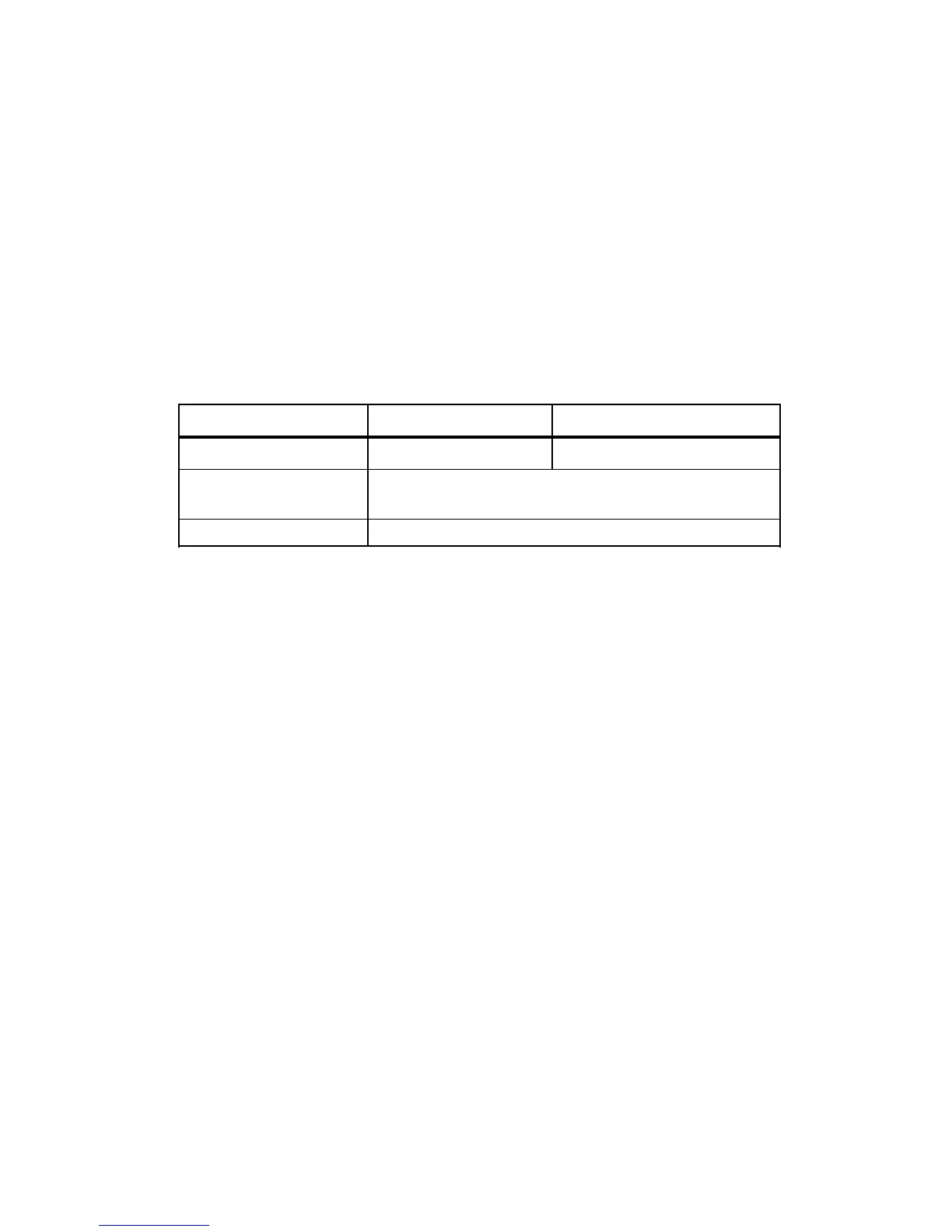
Terminals B, P, B1, B2 1, 2, S3, SC*
Lead Size (AWG) 12 - 10 18 - 14 *
Lead Type 600V ethylene propylene rubber insulated,
or equivalent
Ter minal Screw M4 (resistor end)
* Power leads for the Braking Resistor Unit generate high levels of electrical
noise; therefore, signal leads must be grouped separately.
3. Close and secure the cover of the Braking Resistor Unit terminal box. Close the Drive’s
terminal covers.
4.
Adjustments. Program constant n092 to “ 1 ”; this disables stall prevention during
deceleration.