A6-5
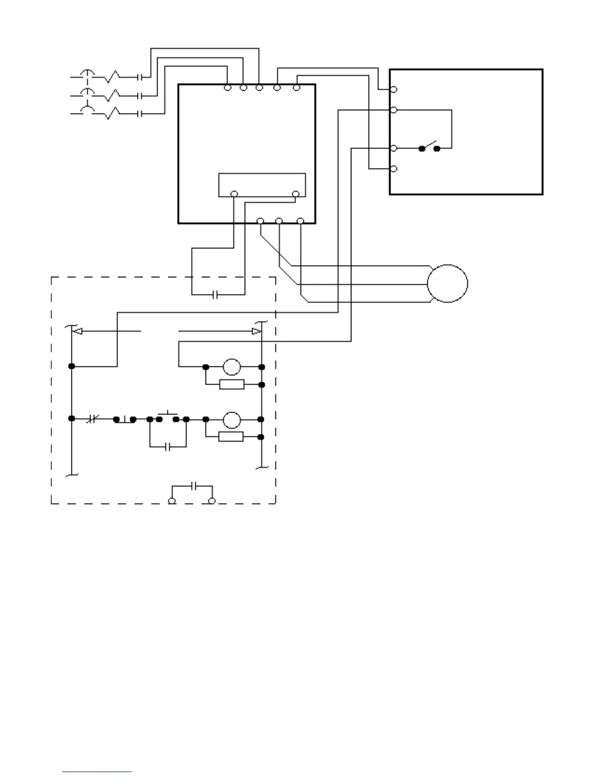
Figure A6-2. Typical Wiring of Braking Resistor Unit
(for 10% Duty Cycle) to Drive
P
2
1
B
THG
BRAKING
RESISTOR
UNIT
(10% DUTY
CYCLE)
PART OF CUSTOMER
SUPPLIED EXTERNAL
CIRCUIT
CONTROL
TERMINAL BLOCK
V7N
NOTE 2
NOTE 1
NOTES:
(1) Wire in series with any other external fault
N.O. contacts connected to the Drive.
(2) Factory default is terminal S3 programmed
for external fault N.O. contact input (2-wire
control). If S3 has been reprogrammed to
another function, one of the other multi-function
terminals must be programmed for external
fault N.O. contact input.
For 3-wire control, connect to one of the
other multi-function input terminals and
program that terminal for external fault
N.O. contact input.
POWER
ON
POWER
OFF
1M
1M
FAULT
CONTACT
RC
RC
120 VAC
THRX
THRX
THRX
THRX
S3
CB
L3
1M
L2
1M
L1
1M
SC
B2
T1
T2
T3
B1
L1(R) L2(S) L3(T)
T1(U) T2(V) T3(W)