EasyManuals Logo

YASKAWA V7 User Manual

YASKAWA V7
157 pages
To Next Page IconTo Next Page
To Previous Page IconTo Previous Page
Page #33 background imageLoading...
Page #33 background image
1-15
Continued
1.4 ELECTRICAL INSTALLATION
L1 ( R )
L2 ( S )
L3 ( T )
FREQUENCY
PULSE TRAIN INPUT
(MAX 30KHz)
SETTING POWER SUPPLY
(+12V, 20mA) (See Note 2)
REFERENCE
FREQUENCY
SETTING
POT
(0 to 10V, 20K /
4 to 20mA, 250)
MIN
SW1 SW2
PNP
NPN
OFF
V
1ON
I
2
MAX
P1
PC
B2B1+2+1
AC
MOTOR
T1 ( U )
T2 ( V )
T3 ( W )
MCCB
L1
L2
L3
S1
FORWARD
RUN/STOP
LOGIC
COMMON
TERMINAL
FREQUENCY
REF.
MULTI-FUNCTION
PHOTOCOUPLER
OUTPUT
48V, 50mA OR LESS
3-PHASE
POWER SUPPLY
(Use L1 (R) and
(Note that drive must
be derated by 50%
on 3-Phase Models)
L2 (S) for
single-phase
input)
MULTI-FUNCTION
OUTPUT CONTACT
250VAC, 1A OR LESS
30VDC, 1A OR LESS
SHIELD
CONNECTION
ANALOG MONITOR
REVERSE
RUN/STOP
S2
S4
S3
S5
S6
FAULT
RESET
EXTERNAL
FAULT
MULTI-STEP
SPEED REF 1
S7
SC
FC
OV
FS
RP
FR
R+
R-
S+
S-
AM
AC
FM
ANALOG OUTPUT
MONITOR 0 to +10VDC
V7
OUTPUT
FREQUENCY
MULTI-FUNCTION
CONTACT INPUT
MA
MB
MC
RUNNING
FAULT
FOR DYNAMIC BRAKING
(See Note 6)
FOR DC REACTOR
(See Note 7)
(See Note 5)
*
P2
SPEED
COINCIDENCE
*
*
(See Note 8)
(See Note 5)
MODBUS
COMMUNICATIONS
RS485/422
19.2 KBPS MAX.
(See Note 4)
(See Note 1)
1RH
MANUAL
SPEED
2K
0-10VDC
or
4-20mA
1OL (See Note 3)
*
*
*
*
+
1OL
See
Note 3)
1R
2K
MULTI-STEP
SPEED REF 2
JOG REFERENCE
MODBUS
(TERMINAL
RESISTANCE:
120, 0.5W)
FIG. 1-9
V74X
OR
1-3FU*
(See Note 9)
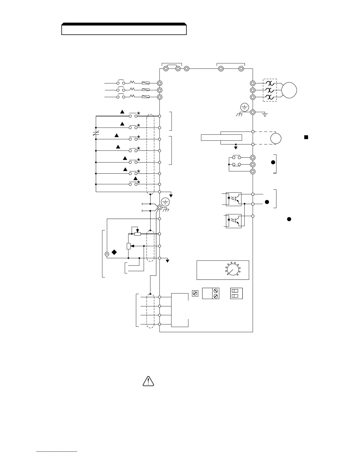
Figure 1-5. Standard Connections (2-Wire Control)
(Parameter n001 set to “10”)
H. Inspection. After wiring is complete, verify that all wiring is correctly installed,
excess screws and wire clippings are removed from inside of unit, screws are
securely tightened, and exposed wire does not contact other wiring or terminals.
If a FWD or REV run command is given from the control
circuit terminal when the operation method selection
function ( n003 ) is set to “ 1 ” and the “LO/RE” selection
is set to “RE”, the motor will start automatically as soon
as power is applied to the main circuit.
CAUTION

Table of Contents

Questions and Answers:

Question and Answer IconNeed help?

Do you have a question about the YASKAWA V7 and is the answer not in the manual?

YASKAWA V7 Specifications

General IconGeneral
ModelV7
CategoryController
ManufacturerYaskawa
Output Frequency0.1 to 400 Hz
TypeAC Drive
Horsepower0.5 to 300 HP
Protection FeaturesOvercurrent, Overvoltage, Undervoltage, Overheating, Short Circuit
Communication InterfacesDeviceNet, Profibus, Ethernet
Operating Temperature-10°C to 50°C
Humidity5% to 95% (non-condensing)
Enclosure RatingIP20
Voltage Class200V, 400V
Storage Temperature-20°C to 65°C

Related product manuals