17-3
IM CW240E
CW 240 Specifications
17
17.1 CW 240 Specifications
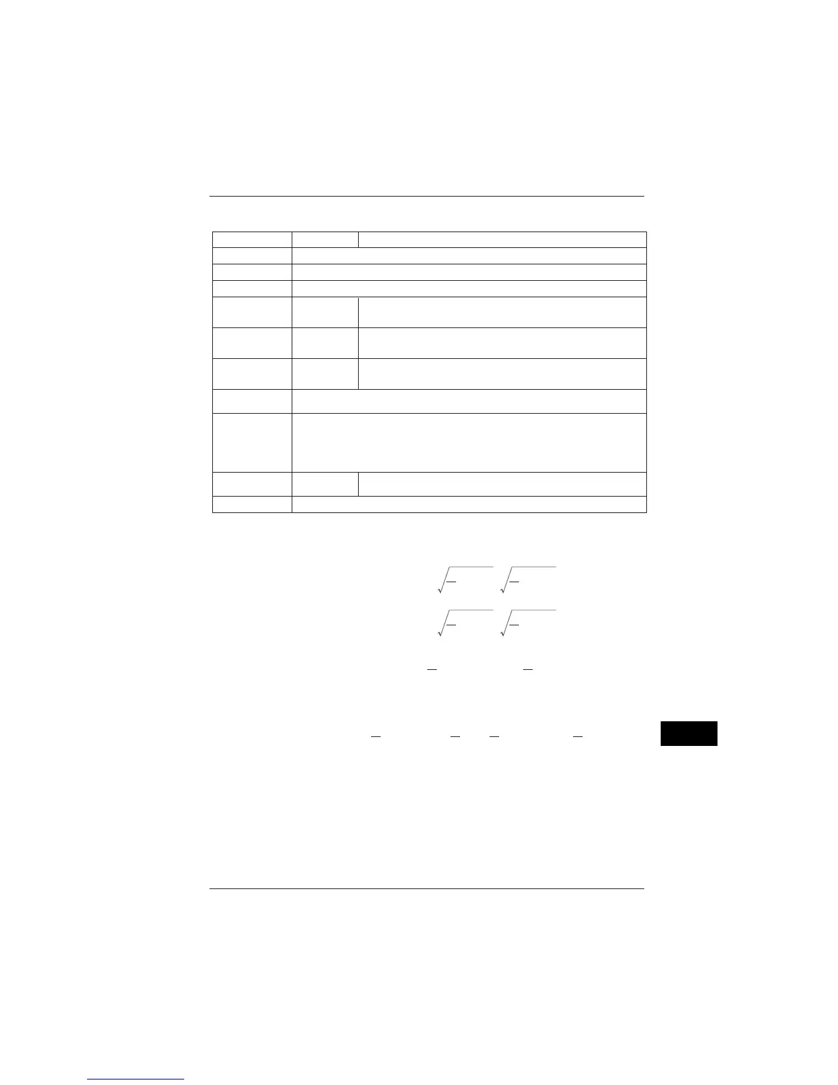
(2) Measurement Functions
Item Voltage
Current/Active Power/Reactive Power 1 (using the reactive power method)
Method
Digital Sampling Method
Frequency Range
45 to 65 Hz (The measurement element is selected from U1, U2, and U3.)
Crest Factor
3 at rated input (1.8 at 1000V range)
Accuracy
Power Factor
Effects
_
Reactive
Factor Effects
Available Input
Range
5 to 110% of each range (The upper limit at 1000V range is 100%.)
Display Range
Temperature
Coefficient
±0.03%rng/°C
±0.05%rng/°C
Display Update Cycle
Approx. 0.5 seconds
Voltage: 0.4 to 130% of each range (zero suppression for under 0.4%)
Electric Power (active, reactive, apparent): 0 to 130% of each range
(zero suppression for 0.17% or less of the range rating)
Harmonics Level: 0 to 130% of each range
Frequency:
_
±0.2%rdg.
±0.1%rng.
96030, 96031,96033,96036 ±0.6%rdg.±0.4%rng.
96032,96034,96035 ±1.0%rdg.±0.8%rng.
96030 ±1.0%rng.(45 to 65Hz,power factor =±0.5)
Excluding 96030 ±2.0%rng.(45 to 65Hz,power factor=±0.5)
96030 ±1.0%rng.(45 to 65Hz,reactive factor=±0.5)
Excluding 96030 ±2.0%rng.(45 to 65Hz,reactive factor=±0.5)
rdg: reading; rng: range
(3) Equations
Voltage RMS Value
U
m
rms = u
m
(t)
2
dt =
∫
T
0
T
1
u
m
(t)
2
∑
T
t=0
T
1
Current RMS Value
I
m
rms = i
m
(t)
2
dt =
∫
T
0
T
1
i
m
(t)
2
∑
T
t=0
T
1
Active Power
P
m
= {u
m
(t)
i
m
(t)}dt =
∫
T
0
T
1
{u
m
(t)
i
m
(t)}
∑
T
t=0
T
1
Reactive Power1: When using the reactive power method
Q
m
=
{
u
m
(t)
i
m
(t
)
}
dt =
∫
T
0
T
1
4
T
4
T
{
u
m
(t)
i
m
(t
)
}
∑
T
t=0
T
1
where
u(t) : Voltage Input Signal
i(t) : Current Input Signal
T : Input Signal 1 Cycle
m : Phase

 Loading...