11
IM 04L05A01-02E
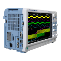
Standard Input Terminals
+/A
/b
CH1
CH2
CH3
CH4
−/B
CH3 CH1
/b
+/A
−/B
CH4
CH2
DX204P, DX208P
Measurement Input
Terminal 1
CH5 to CH8 are assigned (CH1 to CH4 in the above figure correspond to CH5 to CH8
on the terminal 2).
Measurement Input
Terminal 2
(DX208P)
Clamped Input Terminals
DX200P
Standard Input Ternimals
Measurement Input
Terminal 1
DX210P, DX220P,
DX230P
Clamped Input Terminals
+/A
/b
CH1
CH2
CH3
CH4
CH5
CH6
CH7
CH8
CH9
CH10
−/B
CH5 CH3 CH1
/b
+/A
−/B
CH6 CH4 CH2
CH9 CH7
CH10
CH8
DX200P
CH11 to CH20 are assigned (CH1 to CH10 in the above figure correspond to CH11 to CH20
on the terminal 2).
Measurement Input
Terminal 2
(DX220P, DX230P)
CH21 to CH30 are assigned (CH1 to CH10 in the above figure correspond to CH21 to CH30
on the terminal 3).
Measurement Input
Terminal 3
(DX230P)
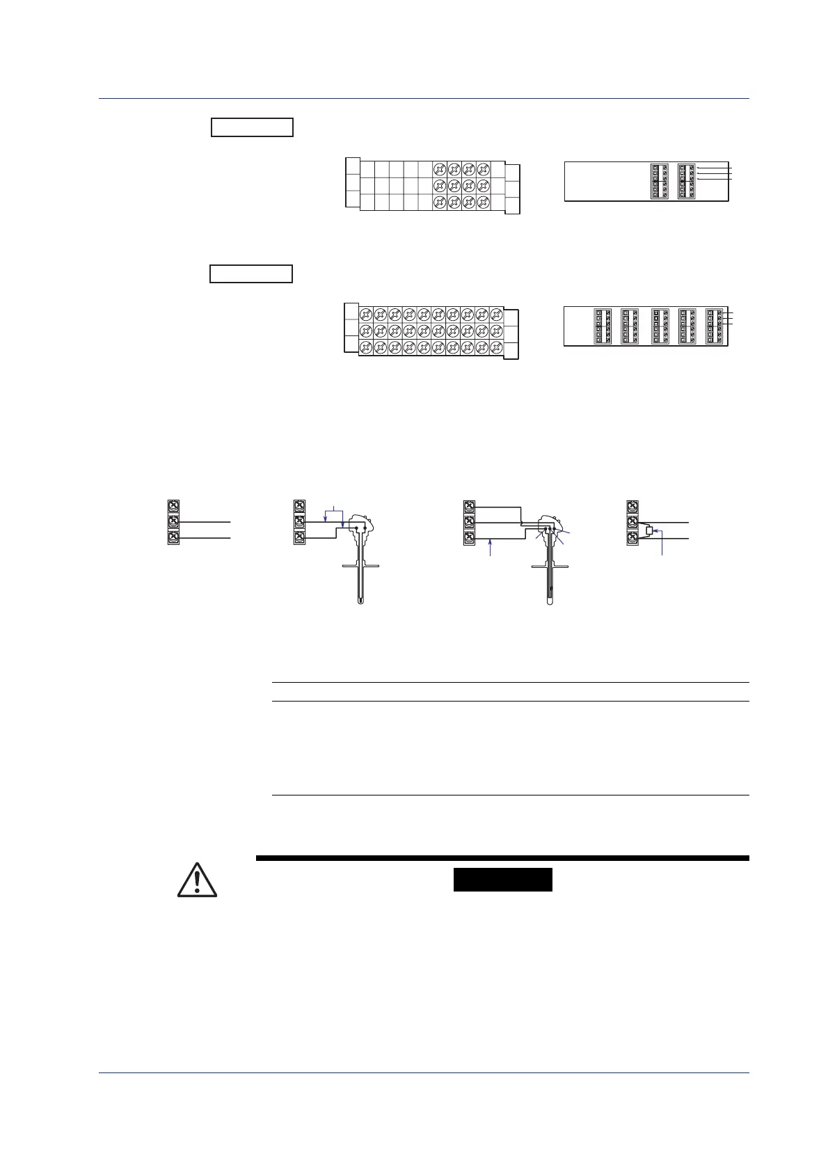
• Wiring Diagram
–
+
+
–
DC voltage input
or DI Input
Thermocouple Input
DC Voltage and DI Input
Resistance Temperature
Detector Input
DC Current Input
DC current input
Shunt resistor
NOTE: For a 4 to 20 mA
input, use a shunt resistor
of 250 Ω ±0.1%.
–
+
–
+
–
+
A
b
Leadwire resistance
: 10 Ω max./wire
(The resistance of the three
wires should be approximately
equal. )
A
b
B
B
Extension leadwire
Power Supply Wiring
Power Supply
Use a power supply that meets the following conditions:
Item except /P1 model /P1 model
Rated power supply 100 to 240 VAC 24 VDC/AC
Allowable power supply voltage range 90 to 132 or 180 to 264 VAC 21.6 to 26.4 VDC/AC
Rated power supply frequency 50/60 Hz 50/60 Hz (for AC)
Allowable power supply frequency range 50/60 Hz±2% 50/60 Hz±2% (for AC)
Maximum power consumption DX100P 45 VA (100 V), 62 VA (240 V) 30 VA (for DC), 45 VA (for AC)
DX200P 75 VA (100 V), 106 VA (240 V) 54 VA (for DC), 76 VA (for AC)
Precautions to Be Taken When Wiring the Power Supply
To prevent electric shock and damage to the DXP, observe the following warnings.
WARNING
Panel Mount Type
• To prevent electric shock, ensure the main power supply is turned OFF.
• To prevent the possibility of fire, use 600 V PVC insulated wire (AWG18) or an
equivalent wire for power wiring.
• Make sure to earth ground the protective earth terminal through a grounding
resistance less than 100 Ω before turning ON the power.
• Use crimp-on lugs (designed for 4 mm screws) for power and ground wiring
termination.
• To prevent electric shock, make sure to attach the transparent terminal cover.
Wiring

 Loading...