<5. Parameter Summary>
5-10
IM 01C25T01-06EN
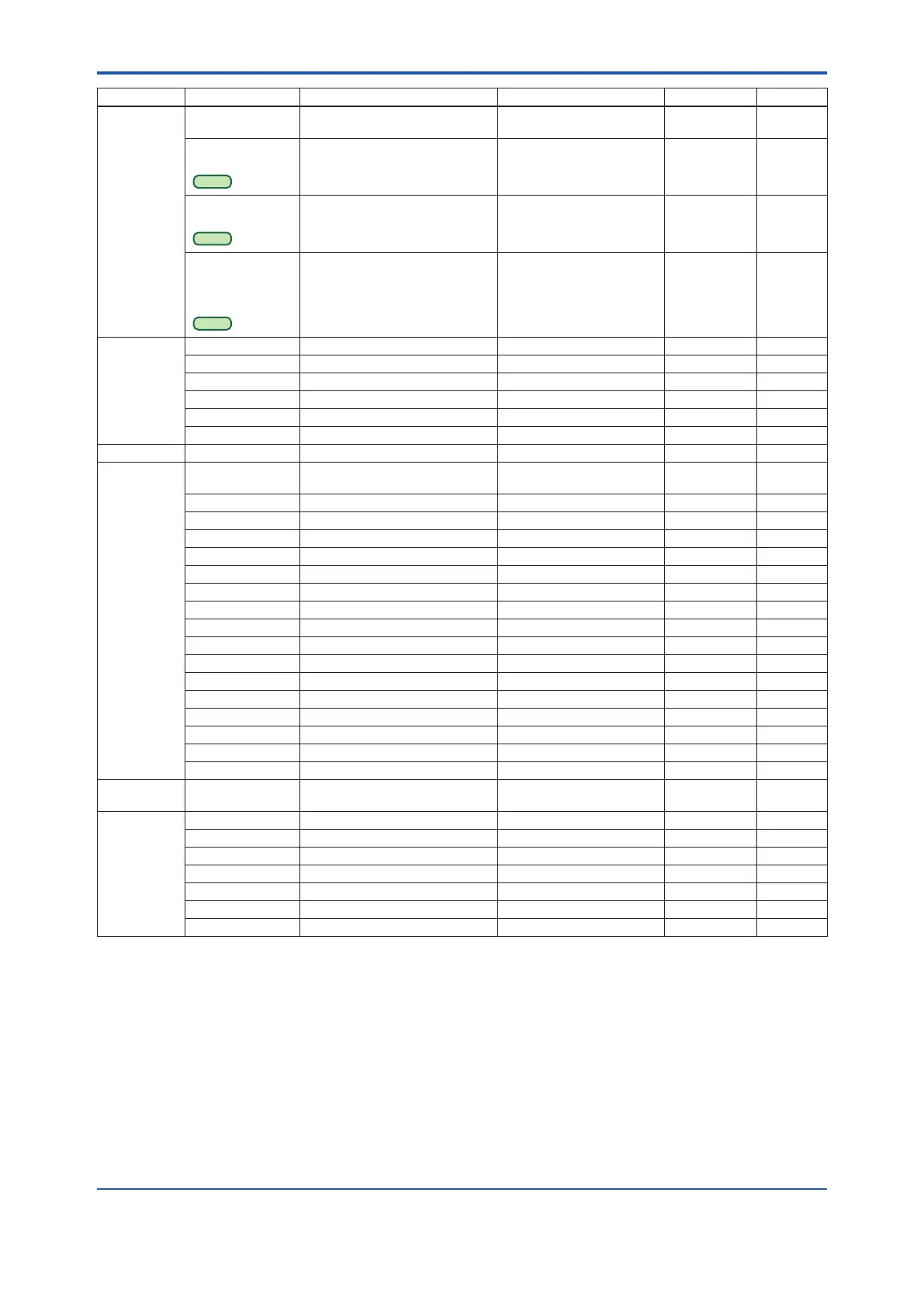
Function Label Item Contents Default value Handling *
1
Process
variables
TV (DD)
Snsr temp (DTM)
Temperature value Capsule temperature R
TV (Temp) Data
Quality
HART 7
Device variable process data
quality
Device variable process data
quality of TV (Temp)
Good R
TV (Temp) Limit
Status
HART 7
Device variable limit status Device variable limit status of
TV (Temp)
Not limited R
TV Update time
period (DD)
Temp update time
(DTM)
HART 7
TV (Temp) Update time period 1s R
Range change Apply values Re range for measured pressure 4 mA, 20 mA, or Exit M
Min Span Minimum span for pressure R
LRV Lower range value for pressure As specied W
LSL Lower sensor limit for pressure R
URV Upper range value for pressure As specied W
USL Upper sensor limit for pressure R
Self test Self test Self-diagnostics M
Sensor trim Clear P snsr trim Reset pressure trim to factory
setting
M
Clear SP snsr trim Reset SP trim to factory setting MD
P LTD Lower pressure trim deviation
*5
R
P LTP Lower temperature trim point
*5
R
P UTD Upper pressure trim deviation
*5
R
P UTP Upper temperature trim point
*5
R
Pres trim Pressure trim M
Pres Zero trim Zeroing M
SP LTD Lower SP trim deviation 0 RD
SP LTP Lower SP trim point SP LRV RD
SP UTD Upper SP trim deviation 0 RD
SP UTP Upper SP trim point SP URV RD
Static Pres trim Static pressure trim MD
Trim Date Trim date **/**/** W
Trim Desc Trim description 16 alphanumerics W
Trim Loc Trim location 8 alphanumerics W
Trim Who Trim person 8 alphanumerics W
Set Diag Mode Set Diag Mode ILBD operation mode Stop, Calculation, or
Reference
WG
Signal
characterizer
Num of points Number of coordinates 0 to 9 9 W
Point setting Coordinates editor M
S.C. Signal characterizer permission Disabled or Enabled Disabled W
X End End point of X 100.00% R
X Start Start point of X 0.00% R
Y End End point of Y 100.00% R
Y Start Start point of Y 0.00% R
*1: Handling:
R
=Read only,
W
=Read & Write,
M
=Method,
A
=Applicable for option code AL,
G
=Applicable for option code DG6,
D
=Applicable for dierential pressure transmitters. Do not change these parameters for pressure transmitters.
*2: Max three Burst Messages (Burst Message 1, Burst Message 2, Burst Message 3)
*3: The default value shows MWP (Maximum working pressure) of the capsule.
Since the working pressure limit varies according to the Model, refer to the General Specications section in each user’s manual.
*4: For output signal code J, refer to the section 3.3.18.
*5: These parameters may contain adjustment values based on the customer range calibration at the factory upon shipment.
When executing “Clear P sensor trim”, P LTD and P UTD will become “0”, and P LTP and P UTP will become the value of LRV and
URV respectively.

 Loading...


