2-7
IM 04L20A01-01E
Installation and Wiring
2
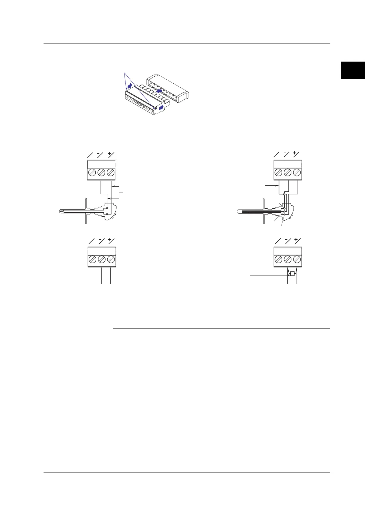
Align the terminal block with the connectors on the main unit,
then push in. Push completely in until it stops.
Reattaching the Terminal Block
3. Attach the terminal cover, then fasten with screws.
Measurement Input Wiring
DC voltage or DI input
Thermocouple input
DC voltage or DI input
Resistance temperature detector input
DC current input
DC current input
A
b
B
b
A
B
b
A
B
b
A
B
Shunt resistor
NOTE: For a 4 to 20 mA
input, use a shunt
resistor of 250 Ω ±0.1%.
Leadwire resistance: 10 Ω max./wire
The resistance of the three wires
should be approximately equal.
Extension
leadwire
b
A
B
–
+
–
+
Note
On the standard measurement input block, RTD input terminals A and B are isolated on each
channel. Terminal b is shorted internally across all channels. If you specified the three-wire
isolated RTD (/N2) option, b terminals are isolated with each other.
2.3 Measurement Input Terminal Wiring
 Loading...


