2-10 IM 04L20A01-01E
2.4 Optional Input/Output Terminal Wiring
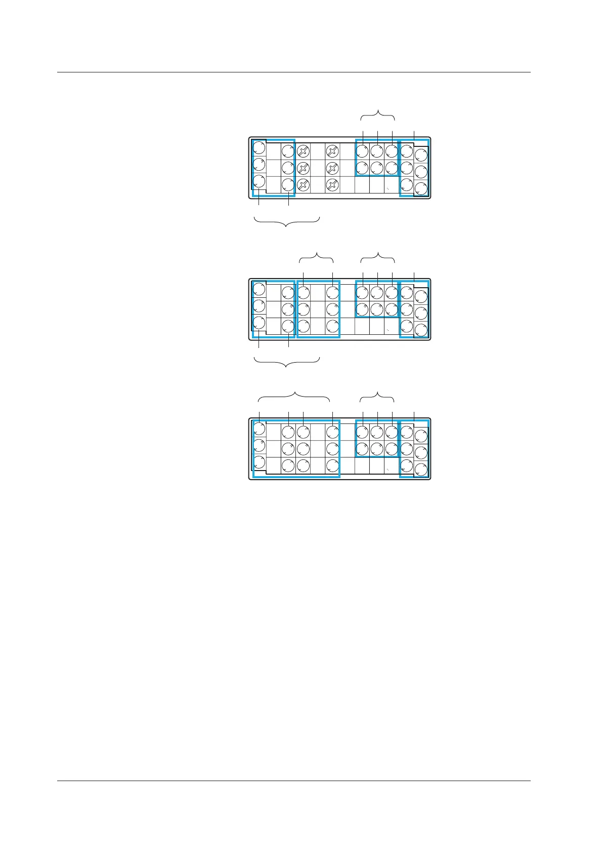
• When pulse input (/PM1) is installed
With /A1
02 01
Pulse input (/PM1)
Remote input (/PM1)8 7 6
FAIL/Memory end output (/F1)
L 4
1
2
5
HH 3
C
C
NO
NC
C
NO
NC
C
NO
NC
L L
C
NO
NC
FAIL
Memory end
Alarm output (/A1)
H
Without alarm
output terminals
Pulse input (/PM1)
Remote input (/PM1)8 7 6
FAIL/Memory end output (/F1)
L 4
1
2
5
HH 3
C
C
NO
NC
L L
C
NO
NC
FAIL
Memory end
H
With /A2
02 01
Pulse input (/PM1)
Remote input (/PM1)04 03 8 7 6
L 4
1
2
5
HH 3
C
C
NO
NC
C
NO
NC
C
NO
NC
L L
C
NO
NC
Alarm output (/A2)
H
NC (normally closed), C (common), NO (normally opened): Relay contact output terminal
1 to 8, C (common): Remote input terminal
H, L: Pulse input terminals
The alarm output terminals 01 to 06 are indicated using [I01] to [I06] in the alarm output
settings.
The remote input terminals 1 to 8 are indicated using numbers 1 to 8 in the remote
output settings.
The pulse input terminals 6 to 8 are indicated using numbers 6 to 8 in the pulse input
settings.
 Loading...


