2-11
IM 04L20A01-01E
Installation and Wiring
2
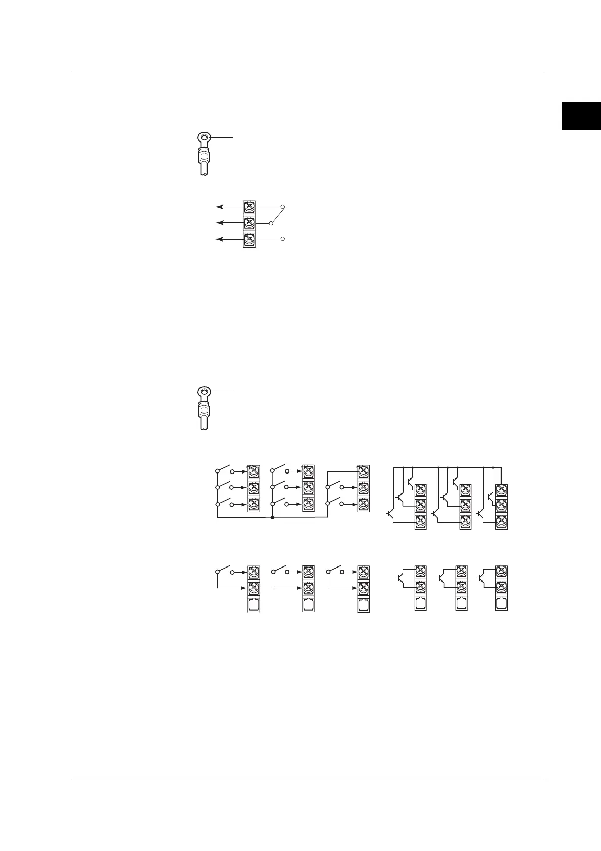
2.4 Optional Input/Output Terminal Wiring
Alarm Output, FAIL/Memory End Output Wiring
Use crimp-on lugs with isolation sleeves (for 4-mm screws) when connecting the input/
output signal wires to the terminals.
Crimp-on lug with isolation sleeve
(for 4-mm screw)
Relay contact output
C
NC
NO
Relay Output Specifications
Output format: Relay contact
Contact rating: 250 VAC (50/60 Hz)/3 A or 250 VDC/0.1 A (resistive load)
Dielectric strength: 1600 VAC (50/60 Hz) for 1 minute (between the input terminal and
earth)
Remote Input, Pulse Input Wiring
Use crimp-on lugs with isolation sleeves (for 4-mm screws) when connecting the input/
output signal wires to the terminals.
Crimp-on lug with isolation sleeve
(for 4-mm screw)
Remote input
C
1
2
3
4
5
6
7
8
• Transistor input (open collector)
• Relay contact input (non-voltage contact)
C
1
2
3
4
5
6
7
8
Pulse input
H
L
H
L
H
L
• Transistor input (open collector)
• Relay contact input (non-voltage contact)
H
L
H
L
H
87 6
678
L
Relay Contact Input and Transistor Input Specifications
Input signal:
• Non-voltage contact:
Close: 200 Ω or less, Open: 100 kΩ or more
• Open collector
0.5 V or less (30 mADC) when turned ON, leakage current of 0.25 mA or less when
turned OFF
Input format: Photocoupler isolation (shared common)
Dielectric strength: 1000 VDC for 1 minute (between the input terminal and earth)
 Loading...


