Quick Reference Instruction Manual for Spare
Sensor replacement
Dismantling of the defective sensor
14 / 76
IM01U10A01-00EN-R, 1
st
edition, 2019-12-09
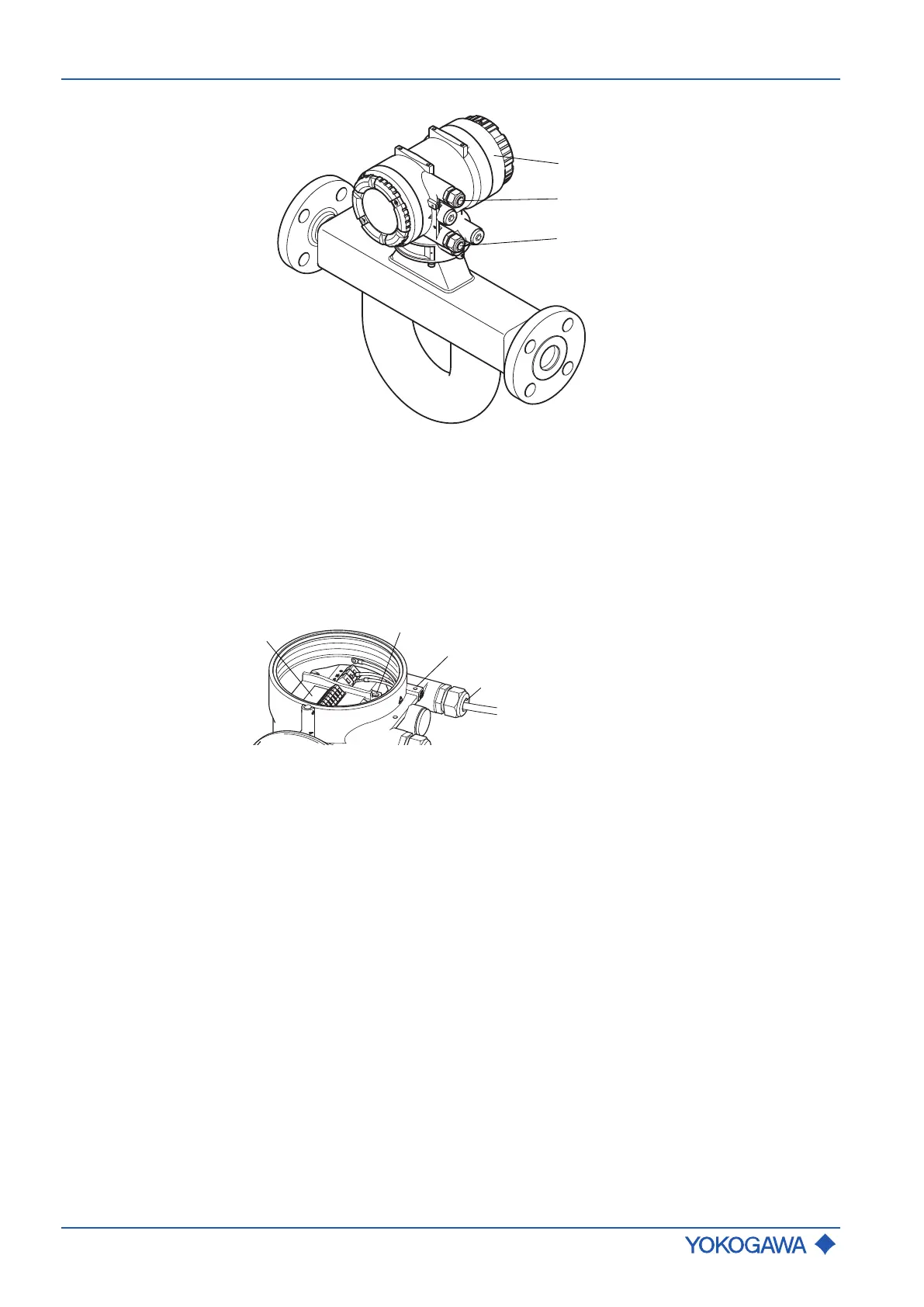
Integral type
Fig.3: Connecting interfaces on sensor integral type
1 Display (if available)
2 Power supply cable entry
3 Communication cable entry
Transmitter
housing
back cover
Fig.4: Connecting interfaces on transmitter housing back cover
1 Terminal box power and I/O
2 Grounding screw for connecting grounding conductor
3 Grounding terminal for external potential equalization (transmitter)
4 Power supply cable entry

 Loading...


