Quick Reference Instruction Manual for Spare
Transmitter replacement
Wiring
66 / 76
IM01U10A01-00EN-R, 1
st
edition, 2019-12-09
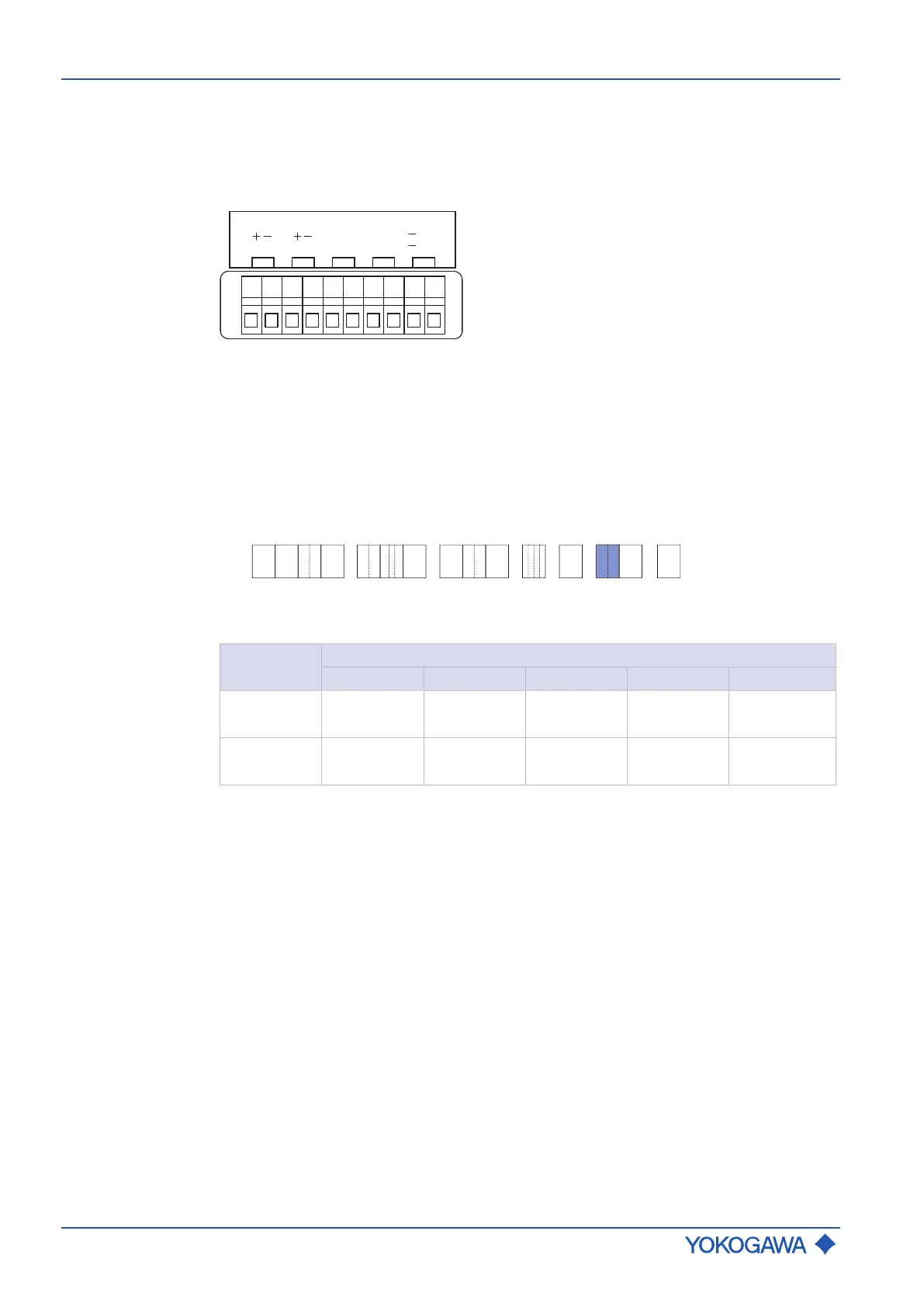
7.4.4.5 PROFIBUS PA connection terminals
For the PROFIBUS PA version there is only one configuration of the connection terminal.
Following is the configuration of the connection terminal (value G0 and G1 on model code
position 13, see Inputs and outputs for details):
PROFIBUS PA
WP
ON/
OFF
PulseFieldbus
(I/O1) (I/O2)
I/O1: Fieldbus PROFIBUS PA communication
I/O2: Pulse Pulse / Frequency output
WP: Write-protect bridge
7.4.4.6 Assignment of PROFIBUS PA
The table below shows possible connection terminal assignments for I/O outputs depend-
ing on model code Position 13.
The following figure shows the relevant position of the model code:
- - - - /-
RC
1 2 3 4 6 75 9 10 11 12 13 14 158
Tab.14: Connection terminal assignment for PROFIBUS PA
Model code
position 13
Connection terminal assignment
I/O1 +/- I/O2 +/- I/O3 +/- I/O4 +/- WP
G0
PROFIBUS
PA
Pulse
Passive
– – Write-protect
G1
PROFIBUS
PA (IS)
Pulse
Passive (IS)
– – Write-protect
PROFIBUS PA: PA communication
Pulse Passive: Pulse / Frequency output
Intrinsically safe (IS) outputs are only available in combination with selecting Ex approval
of the device, see General Specifications (GS) GS01U10B␣␣-00␣␣-R, chapter Ex ap-
proval.
 Loading...


