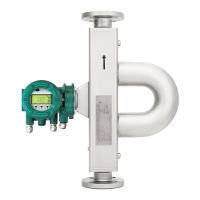
Quick Reference Instruction Manual for Spare
Transmitter replacement
Wiring
56 / 76
IM01U10A01-00EN-R, 1
st
edition, 2019-12-09
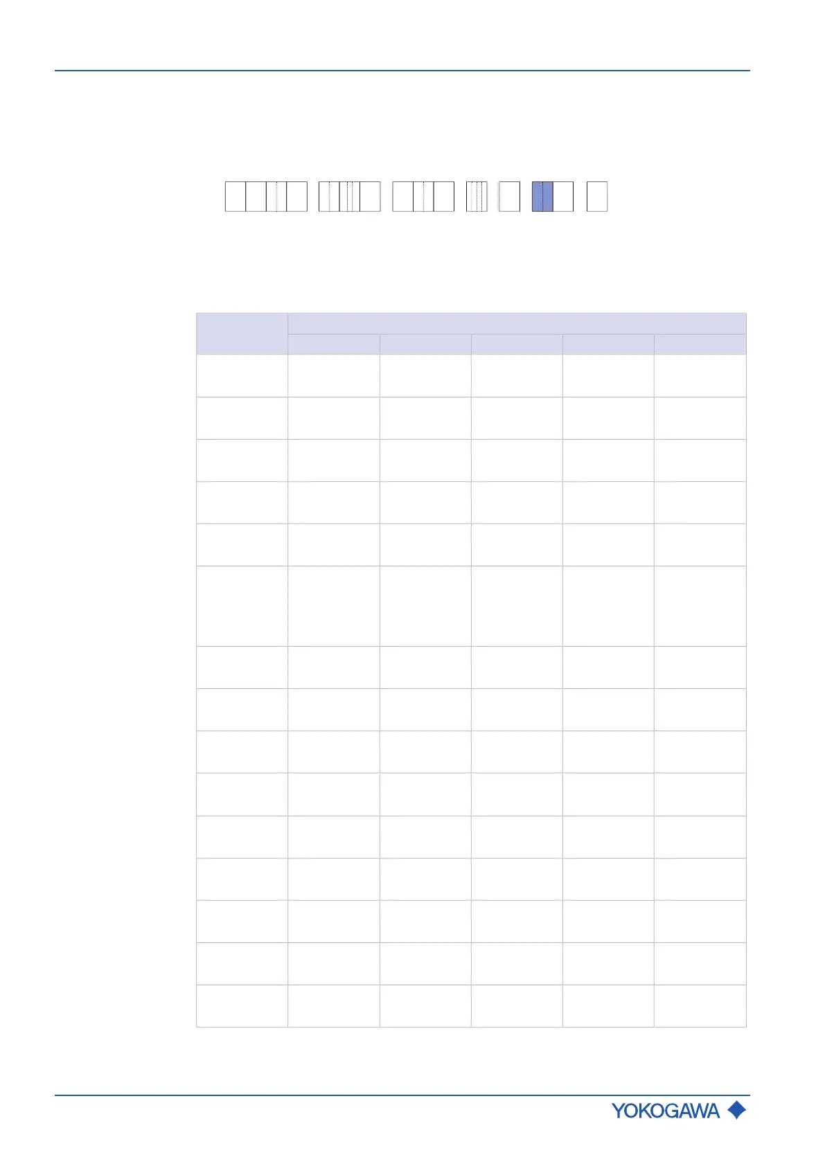
7.4.4.3 Assignment of HART and Modbus
The table below shows possible connection terminal assignments for I/O outputs depend-
ing on model code position 13.
The following figure shows the relevant position of the model code:
- - - - /-
RC
1 2 3 4 6 75 9 10 11 12 13 14 158
Configuration of input/output terminals for HART communication
HART I/O Tab.11: Connection terminal assignment for HART
Model code
Position 13
Connection terminal assignment
I/O1 +/- I/O2 +/- I/O3 +/- I/O4 +/- WP
JA
Iout1
Active
P/Sout1
Passive
– – Write-protect
JB
Iout1
Active
P/Sout1
Passive
P/Sout2
Passive
Iout2
Active
Write-protect
JC
Iout1
Active
P/Sout1
Passive
Sin
Iout2
Active
Write-protect
JD
Iout1
Active
P/Sout1
Passive
Sout
Passive
P/Sout2
Passive
Write-protect
JE
Iout1
Active
P/Sout1
Passive
Sin
P/Sout2
Passive
Write-protect
JF
Iout1
Active
P/Sout1
Passive
Sin
P/Sout2
Active
Internal pull-
up resistor
Write-protect
JG
Iout1
Active
P/Sout1
Passive
Sin
P/Sout2
Active
Write-protect
JH
Iout1
Active
P/Sout1
Passive
Iout2
Passive
Iin
Active
Write-protect
JJ
Iout1
Active
P/Sout1
Passive
P/Sout2
Passive
Iin
Active
Write-protect
JK
Iout1
Active
P/Sout1
Passive
Sin
Iin
Active
Write-protect
JL
Iout1
Active
P/Sout1
Passive
Iout2
Passive
Iin
Passive
Write-protect
JM
Iout1
Active
P/Sout1
Passive
P/Sout2
Passive
Iin
Passive
Write-protect
JN
Iout1
Active
P/Sout1
Passive
Sin
Iin
Passive
Write-protect
JP
Iout1
Passive
P/Sout1
Passive
Iout2
Passive
– Write-protect
JQ
Iout1
Passive
P/Sout1
Passive
Iout2
Passive
P/Sout2
Passive
Write-protect
 Loading...


