Quick Reference Instruction Manual for Spare
Transmitter replacement
Wiring
54 / 76
IM01U10A01-00EN-R, 1
st
edition, 2019-12-09
7.4.4 Transmitter
7.4.4.1 Connection terminals
WARNING
Risk of injury from electrical shock due to inadequate grounding
▶ Use grounding screw to connect the grounding conductor.
▶ Use an M4 ring-type or forked cable lug for the grounding conductor of the power
supply cable.
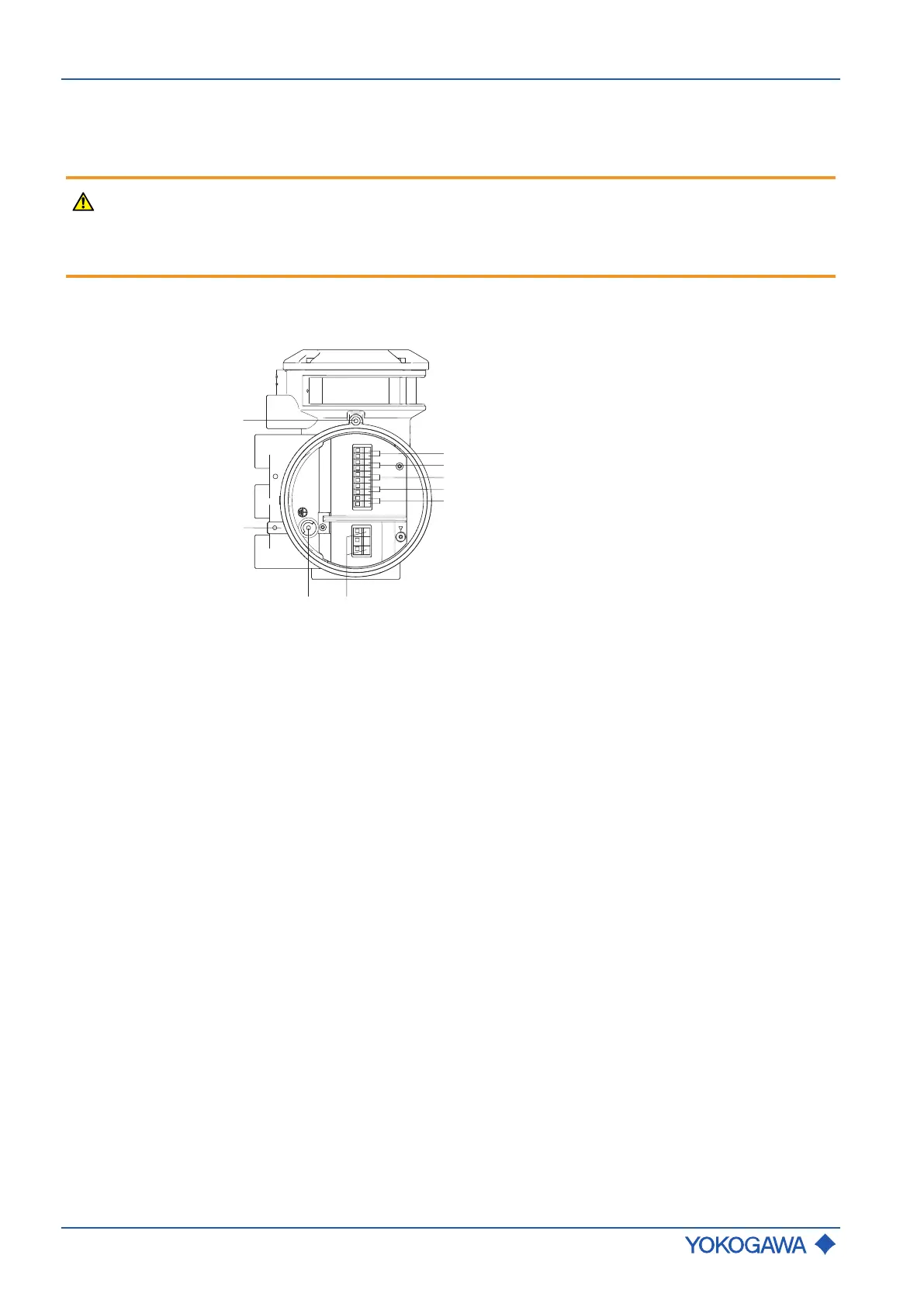
Terninal box for I/O
Fig.29: Terminal for I/O outputs and power supply in transmitter
1 Power supply connection terminals 6 Connection terminals for I/O2 +/-
2 Grounding screw in terminal box 7 Connection terminals for I/O3 +/-
3 Grounding terminal 8 Connection terminals for I/O4 +/-
4 Locking screw 9 WP: Write-protection terminal
5 Connection terminals for I/O1 +/-

 Loading...


