Wiring
Quick Reference Instruction Manual for Spare
Transmitter replacement
IM01U10A01-00EN-R, 1
st
edition, 2019-12-09
55 / 76
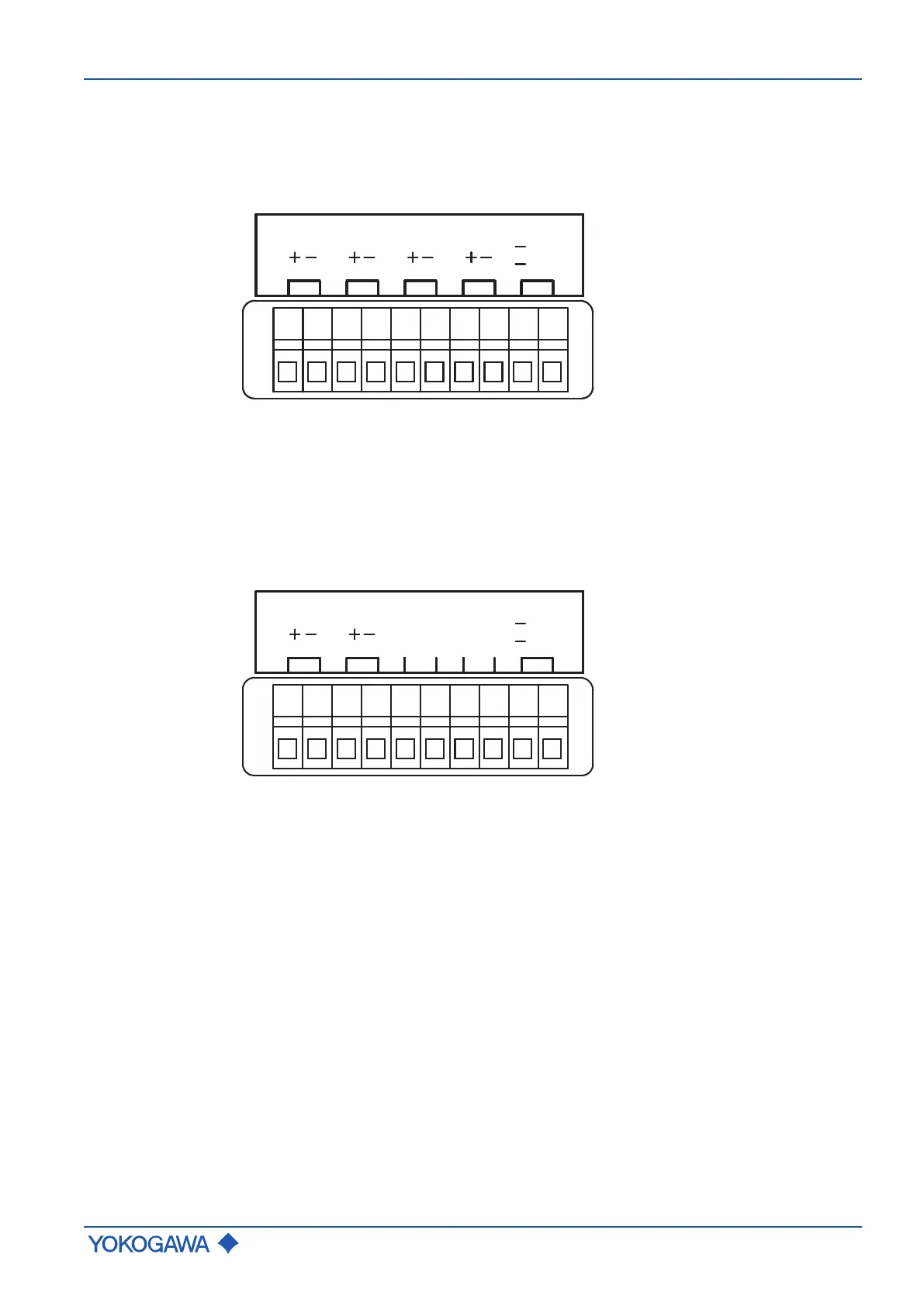
7.4.4.2 HART and Modbus connection terminals
Depending on the flow meter specification, there are different configurations of the
connection terminal. Following are configuration examples of the connection terminal
(value JK and M7 on model code position 13 - see Inputs and outputs for details):
HART
WP
ON/
OFF
P/Sout1
Iout1
(I/O1) (I/O2)
Sin
(I/O3) (I/O4)
Iin
I/O1: Iout1 Current output (active/passive)
I/O2: P/Sout1 Pulse or status output (passive)
I/O3: Sin Status input
I/O4: Iin Current input (active/passive)
WP: Write-protect bridge
Modbus
WP
ON/
OFF
P/Sout1
Iin
(I/O1) (I/O2)
Modbus
(I/O3) (I/O4)
C AB
I/O1: Iin Current input (passive)
I/O2: P/Sout1 Pulse or status output (passive)
I/O3-I/O4: Modbus RS485 input/output
WP: Write-protect bridge
 Loading...


