Aliasing
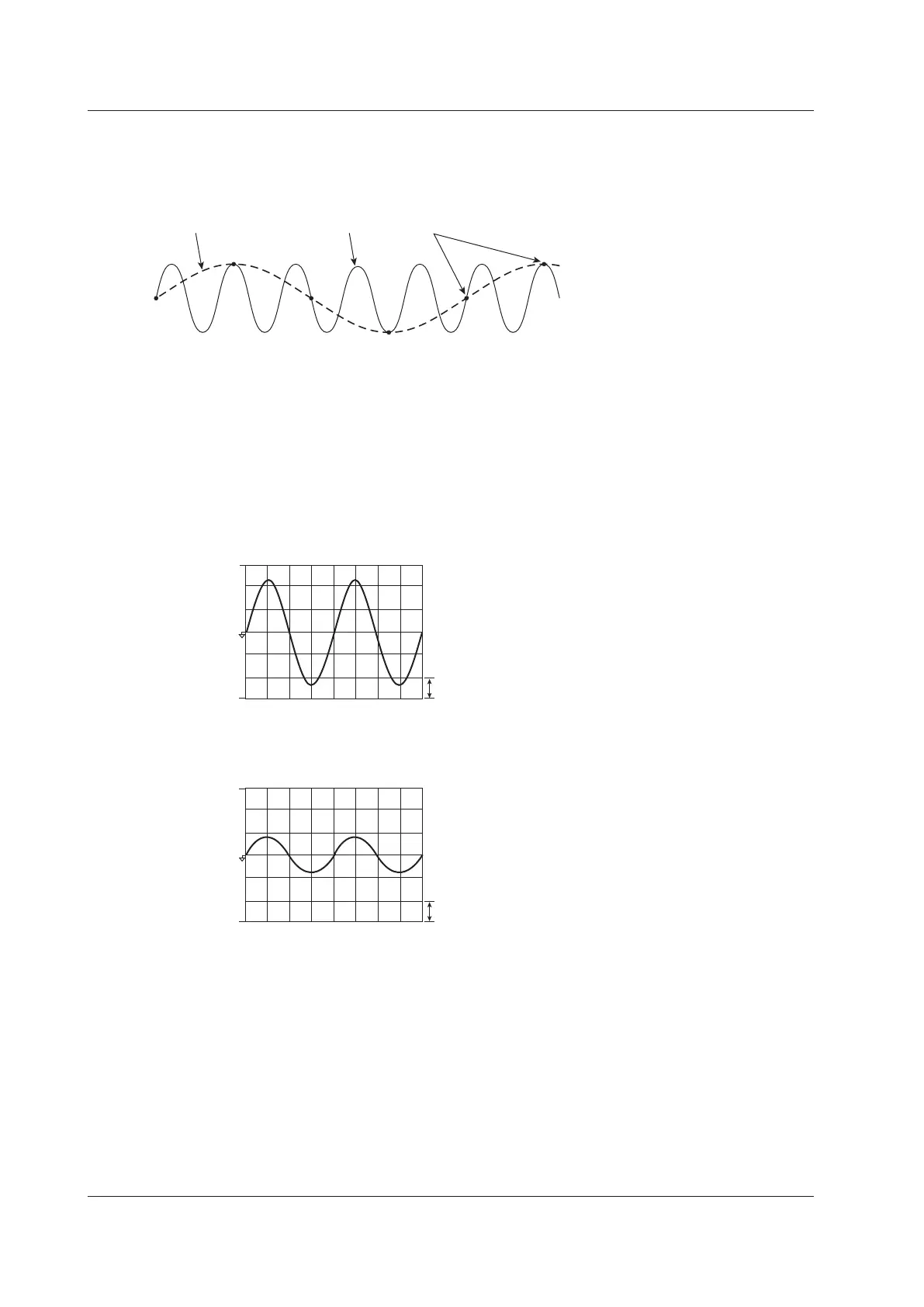
When the sample rate is low compared to the frequency of the input signal, the high frequency components of
the signal are lost. In accordance with the Nyquist sampling theorem, the high frequency components in the
signal are misread as low frequency components. This is called aliasing.
Aliased signal Input signal Sampled points
Vertical Axis (Amplitude)
The height (display range) of the vertical axis is based on the specified crest factor and measurement range.
For example, if the crest factor is set to CF3 and the voltage measurement range is set to 100 Vrms, the display
range is set to ±300 Vpk (±3 × 100 Vrms) with the zero input line at the center. The waveform is clipped if this
range is exceeded.
In the same way, if the crest factor is set to CF6 and the voltage measurement range is set to 50 Vrms, the
display range is set to ±300 Vpk (±6 × 50 Vrms) with the zero input line at the center.
1 grid division
= 100 V
When measured with a measurement
range of 100 Vrms
Input zero line
300 Vpk
–300 Vpk
1 grid division
= 300 V
When the same signal is measured
with a measurement range of 300 Vrms
900 Vpk
–900 Vpk
10 Waveform Display

 Loading...


