8-9
IM WT1801-01EN
Type 3 (The method used in the harmonic measurement modes of the WT1600, WT3000 and PZ4000)
The WT1800 calculates the reactive power of each phase using equation 2 and calculates the three-phase
apparent power using equation 4. This equation is available on models with the harmonic measurement option
or the simultaneous dual harmonic measurement option.
Active power for a three-phase, four-wire system
PΣ = P1 + P2 + P3
Apparent power for a three-phase, four-wire system
Reactive power for a three-phase, four-wire system QΣ = Q1 + Q2 + Q3
Corrected Power Equation (Pc Formula)
Some standards require that a voltage transformer’s active power be corrected when the load connected to the
voltage transformer is very small. You can select an equation to use for this correction and specify the coefficient.
Applicable Standard (Select standard)
Select from the following.
• IEC76–1 (1976)
•
IEC76–1 (1993)
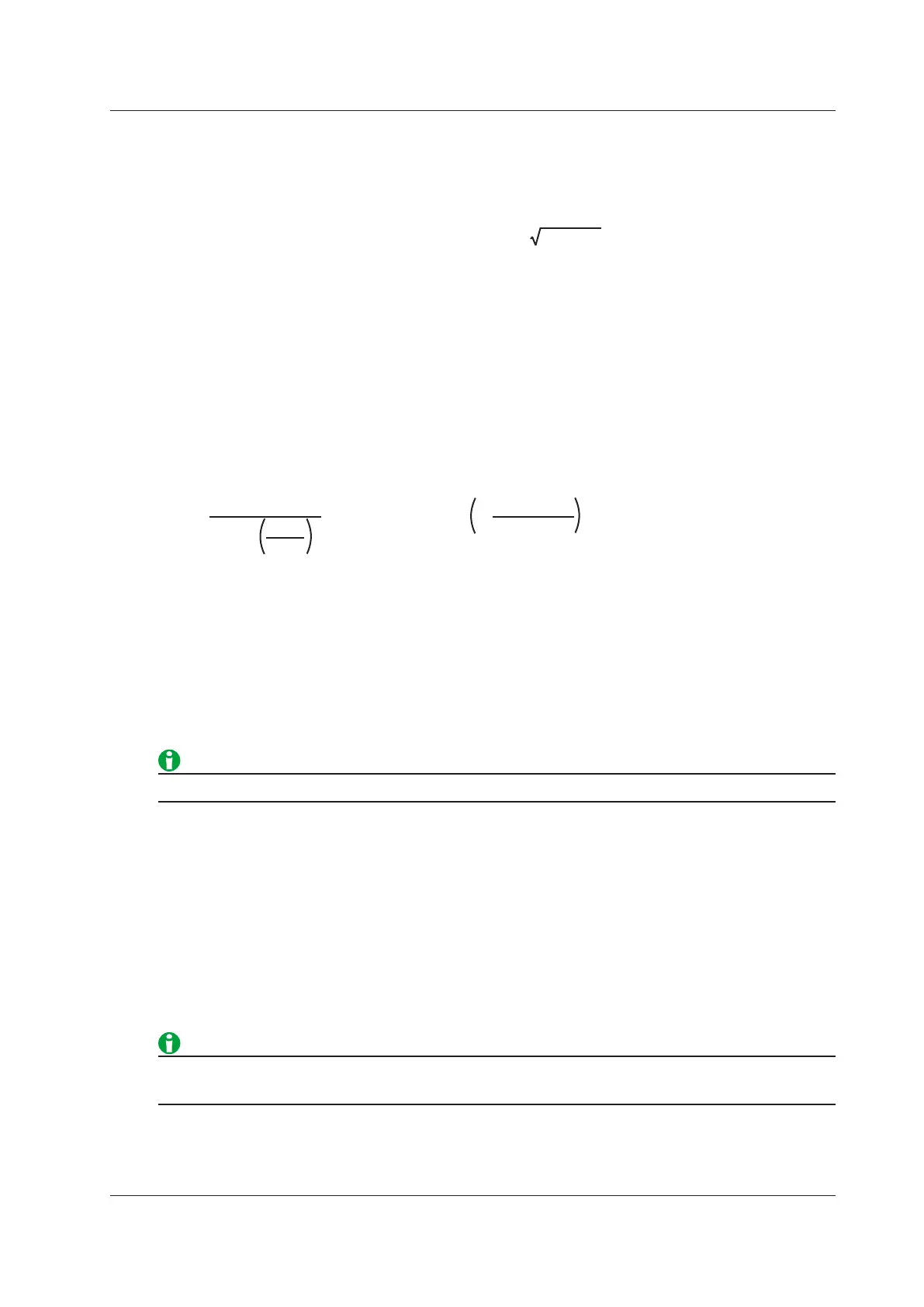
Equations for each applicable standard
P
P
1+P2
Urms
Umn
2
Pc=
P
Umn
−
Urms
Umn
1+
Pc=
IEC76-1(1976) IEC76-1(1993)
Pc: Corrected power
P: Active power
Urms: True rms voltage
Umn: Voltage’s rectified mean calibrated to the rms value
P1, P2: Coefficients specified by the applicable standard
Coefficients (P1 and P2)
You can set coefficients P1 and P2 to values within the range of 0.0001 to 9.9999.
The IEEE C57.12.90-1993 equation is the same as IEC761(1976).
Sampling Frequency (Sampling Frequency)
The WT1800 offers three types of sampling frequencies, each approximately 2 MHz, to prevent the input
waveform from being measured as a DC signal because of aliasing. You can choose to automatically switch the
sampling frequency or choose to use a fixed frequency.
•
Auto:
The WT1800 automatically switches between clocks A, B, and C.
• Clock A: 2.000000 MHz
• Clock B: 1.941176 MHz
• Clock C: 1.885714 MHz
• Set the sampling frequency to Auto to prevent the measured values from being distorted by aliasing.
• If you want to use a fixed sampling frequency, select a frequency from Clock A to Clock C.
8 Computation

 Loading...


