10-1
IM WT1801-01EN
10 Waveform Display
Waveform Display (WAVE)
You can press WAVE to make the waveform displays of the following types of input signals.
• Input element voltage and current
• Motor evaluation function (option) speed and torque
• Auxiliary inputs (option) Aux1 and Aux2
Each time you press WAVE, the number of split screens switches in order between none, 2, 3, 4, and 6.
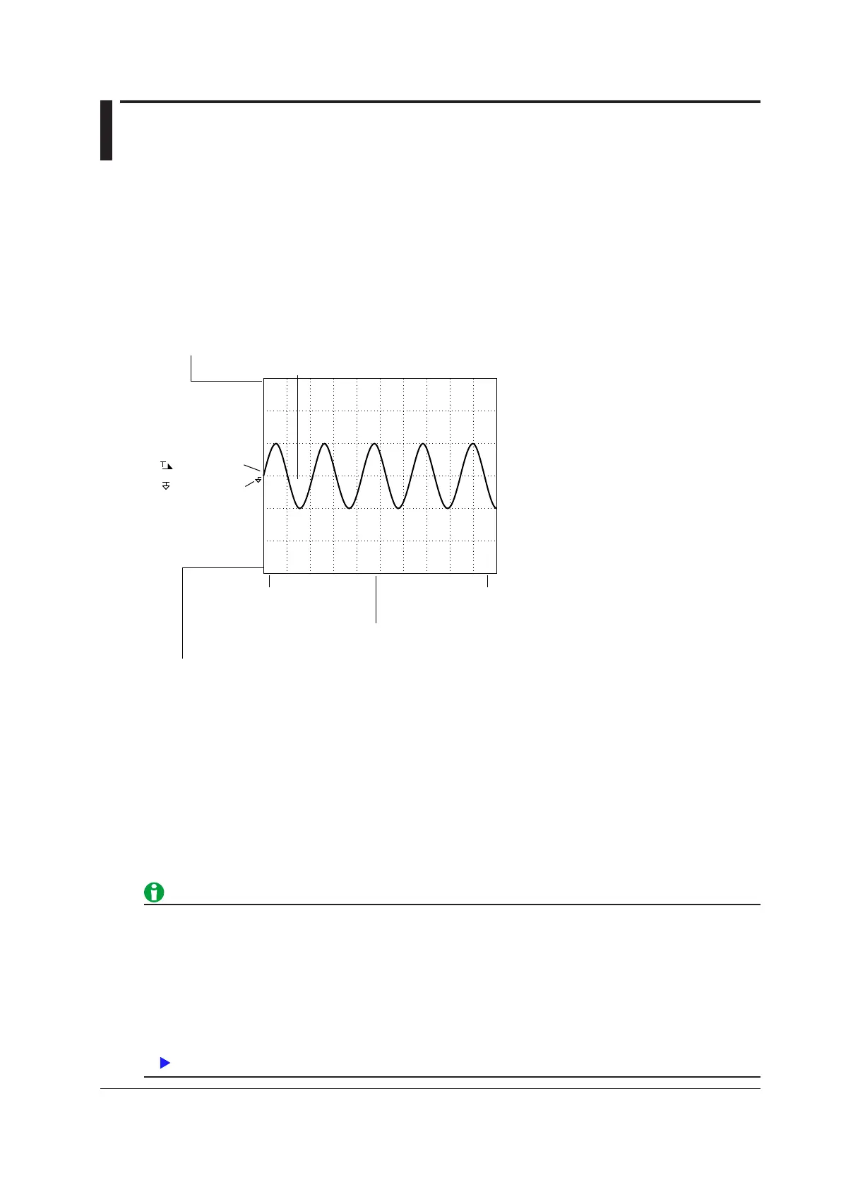
Waveform Display Example
Time at the right edge of the screen
(amount of time contained in the screen)
Time at the left edge of the screen
(fixed at 0 seconds)
• The number of data points between the left and right edges of the display.
• “P-P” indicates that the displayed waveform has been P-P compressed.
Scale Value
The measurement function, the element number, and the upper limit
of the displayed waveform
Scale Value
The measurement function, element number, and lower limit of the displayed waveform
Trigger level
Ground level
Waveform label
U1 3.000kV
U1
−
3.000kV
0.000s
50.000ms
<< 1602 (p
−p)
>>
U1
Measurement Mode during Waveform Display
If the measurement mode display is set to Normal Mode (Trg), measurement takes place from when a trigger is
detected over the data update interval. The following amount of time is required for the WT1800 to compute the
measured data, process it for displaying, and so on, and become ready for the next trigger.
•
When the data update interval is 50 ms to 500 ms:
Approx. 1 s
• When the data update interval is 1 s to 5 s: Data update interval + 500 ms
In this case, storage, communication output, and D/A output operate in sync with the triggers.
If the measurement mode display is set to Normal Mode, storage, communication output, and D/A output operate
in sync with the data update interval.
• If you do not set the trigger level properly, the waveform display start point (the signal level on the left edge
of the screen) may be unstable, or waveforms may not appear.
• Even when waveforms are displayed, in the following situation
s, the measurement mode indication at the
upper left of the screen is Normal Mode.
• During integration
•
When the trigger mode is OFF
In Normal Mode, measurements are taken and the sampled data is updated automatically at the data
update interval. In this mode, there are limitations on the waveform display feature.

 Loading...


