8-20
IM 01C50C05-01EN
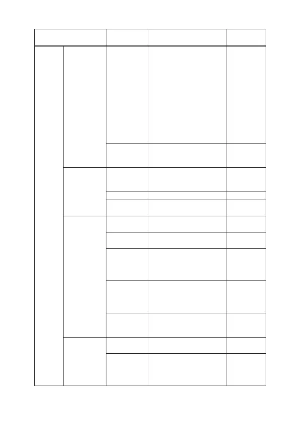
Item
Parameter
name
Descriptions Initial setting
Setup Trim Setup Minimum
Lower Trim
Point Value
/Maximum
Lower Trim
Point Value
/Minimum
Upper Trim
Point Value
/Maximum
Upper Trim
Point Value
Maximum/minimum values
for trimming point
N/A
Minimum
Dierential
Trim
Minimum value of the
dierence of lower and
upper trimming point
N/A
Signal
Condition
Upper Sensor
Limit/Lower
Sensor Limit
Maximum/minimum values
for device variables range
Depend on
sensor setup
Units Device variables unit degC
Damping Value Damping time constant in
seconds: 0.4 to 60.0s
*1
Output
Condition
→ Analog
output
Loop current
<PV AO>
Output value in mA N/A
Loop current
mode
Loop current setting at
multidrop
O
Loop test Change the output manually
for testing the loop. 4mA,
20mA, or value within 3.5
to 23mA
N/A
D/A trim Allows the calibration of a
selected analog output with
an external reference at the
operating endpoint
N/A
Override D/A
trim <Clear D/A
trim>
Overrides any previous D/A
trimming by restoring factory
calibration values
N/A
Output
Condition
→ Analog
output
→ Output
range
AO 0%(100%) Output value for 0% (100%)
in mA.
4mA (20mA)
AO
lower(upper)
Limit
Output lower (upper) limit in
mA. NAMUR, or 3.8 to 23mA
3.8mA
(20.5mA)

 Loading...


