JOHNSON CONTROLS
199
SECTION 7 - OPERATION
FORM 201.23-NM2
ISSUE DATE: 09/25/2020
7
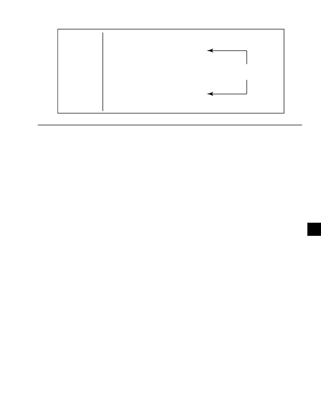
The Setpoint is the Leaving Chilled Liquid Tempera-
ture midpoint of the Control (Cooling) Range. The
Setpoint High Limit is the Setpoint plus the Control
Range. The Setpoint Low Limit is the Setpoint minus
the Control Range. The chiller will attempt to con-
trol within the temperature range programmed by the
Setpoint plus or minus CR.
Starting and stopping of compressors will be handled
by the Standard or High IPLV Capacity Control Rou-
tine. Loading and unloading will be controlled by tem-
perature offset and rate by the Fuzzy Logic Control
Routine.
A graphical representation of the Setpoint and high and
low limit (plus or minus CR) are shown in Figure 49
on page 199.
NUMBER OF COMPRESSORS TO START
General
The number of compressors to start control logic varies
between the standard and optional High IPLV chillers.
Standard IPLV chiller control utilizes sequential logic
that requires the microprocessor to start 1 compressor
at a time and only add a compressor when all running
compressors reach maximum speed. Optional High
IPLV chillers have control algorithms that provide
“smart” anticipatory control to determine how many
compressors need to be started to satisfy the current
load. The “smart” logic is capable of reducing short
cycling, and reducing loading time on a hot water start,
and starting all compressors at the same time.
Standard IPLV
The Standard IPLV control always starts a single com-
pressor under all circumstances as the first step of
loading. The Chiller Control Board does not make de-
cisions on the number of compressors to start based
on chilled liquid temperatures and prior compressor
operation when starting the chiller. An additional com-
pressor is only started when the lead compressor has
reached maximum speed and cooling requirements are
not satisfied.
Optional Optimized High IPLV
On optimized IPLV chillers, the Number of
Compressors to Start Logic will be used to determine
how many compressors should be run when the unit
starts from the all compressors stopped state. This rou-
tine will try to run all the compressors unless it is deter-
mined that less will be needed due to light load.
The first step in the sequence is for the microprocessor
to set the number of compressors to start equal to the
number of compressors in the chiller. The micropro-
cessor will look at two prior conditions relating to the
compressor operating time the previous time it ran and
how long the last compressor has been off along with
two indicators of chilled liquid load requirements (rate
of change of chilled liquid temperature and deviation
from setpoint). Temperature deviation is the amount of
error compared to the setpoint high limit (Setpoint plus
CR). Based on this information, the microprocessor
will then determine the number of compressors to start.
The flowchart in Figure 50 on page 200 describes the
compressor starting decision process.
It is desirable to run as many compressors as possible
for increased efficiency. Optimized logic will keep as
many compressors on line and reduce speed in an ef-
fort to optimize the use of the entire evaporator tube
surface.
48˚F --------------------------------------------------
46˚F ---------
Setpoint + CR ( Setpoint High Limit)
----------
Programmed
44˚F ----------
Setpoint
---------------------------------
Control (Cooling) Range
42˚F --------------------
Setpoint – CR (Setpoint Low Limit)
40˚F
38˚F --------------------------------------------------
--------------------------------------------------
FIGURE 49 - CHILLER CONTROL (COOLING) RANGE
LD10625

 Loading...


