JOHNSON CONTROLS
229
SECTION 8 - MICROPANEL
FORM 201.23-NM2
ISSUE DATE: 09/25/2020
8
A fault acknowledge bit from the Chiller Control
Board is sent to the VSD via comms after receiving
valid fault data from the VSD. When the VSD Logic
Board receives the fault acknowledge via comms from
the panel it will reset (close) the Fault Relay. The fault
acknowledge is reset by the Chiller Control Board after
the Fault Relay is closed by the VSD Logic Board.
VSD Fault Compressor Start Inhibit
If a VSD fault condition exists while the compressor is
not running or pre-charging, the Chiller Control Board
will not try to start the faulted compressor(s). The start
inhibit will be automatically cleared when the fault
condition goes away.
UNIT WARNINGS
Unit Warning Operation
Unit warnings are caused when a condition is pres-
ent requiring operator intervention to restart the unit.
All setpoints, program values, and options should be
checked before operating the unit. Warnings are not
logged to the history buffer. If a unit warning is in
effect, the message will be displayed to the operator
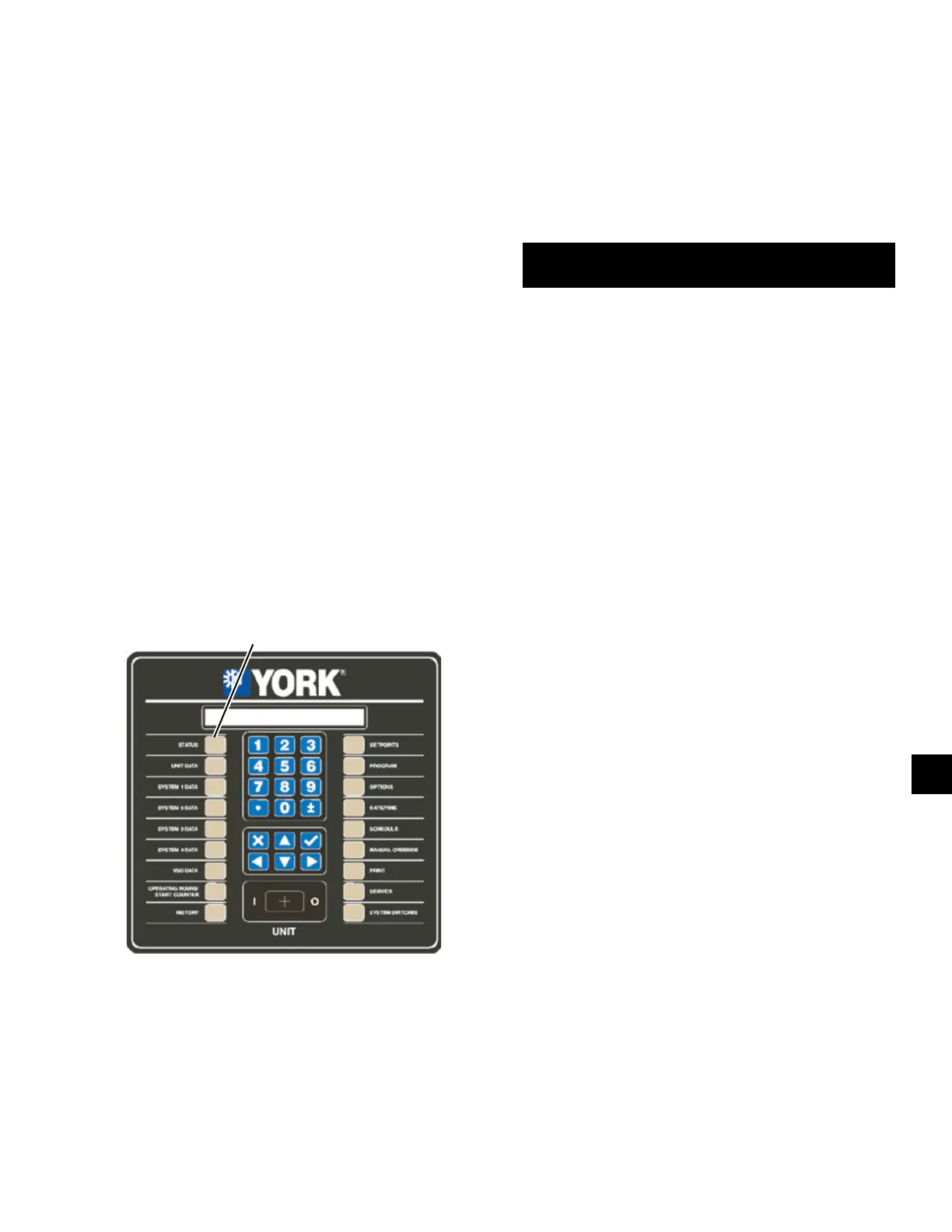
when the STATUS key is pressed.
LD10605
STATUS
KEY
Low Battery Warning
The LOW BATTERY WARNING can only occur at
unit power-up. On micropanel power-up, the RTC bat-
tery is checked to see if it is still operational. If it is,
normal unit operation is allowed. If the battery voltage
is determined to be low, the following warning mes-
sage is displayed indefinitely.
UNIT WARNING: !! LOW BATTERY !!
CHECK SETPOINTS/PROGRAM/OPTIONS/TIME
If a low battery condition exists, all programmed
setpoints, program values, time, schedule, and history
buffers will have been lost. These values will all be re-
set to their default values, which may not be the desired
operating values. Once a bad battery is detected, the
unit will be prevented from running until the MANU-
AL OVERRIDE key is pressed. Once the MANUAL
OVERRIDE key is pressed, the anti recycle timers will
be set to the programmed default anti recycle time to
allow the operator sufficient time to check setpoints,
program values, etc.
If a low battery is detected, it should be replaced as
soon as possible. The programmed values will all be
lost and the unit will be prevented from running on the
next power interruption. The RTC/Battery is located on
the Chiller Logic Board shown in Figure 60 on page
230.
MICROBOARD (331-03478-XXX)
The 331-03478-xxx microboard was developed as a
direct replacement for the 031-02478-xxx line of mi-
croboards. No adapter harness is required when replac-
ing a 02478 with the new 03478. The 03478 uses the
IPUII processor card and provides some new features
for the chillers that the 02478 did not have. The 03478
program resides in flash memory instead of EPROM.
Program updates are accomplished by loading the new
program from an SD card inserted into the SD card
reader/writer. This same SD card reader/writer also al-
lows the user to datalog the operating parameters to an
SD card every 5 seconds. This information is invalu-
able when troubleshooting unit and system problems
since it allows the service technician to view operat-
ing parameters prior to a unit fault. Details on the new
datalogging capability are explained in the OPTIONS
Key area of this manual. A Real Time Clock/BRAM
keeps time and setpoints during power outtages.

 Loading...


