JOHNSON CONTROLS
201
SECTION 7 - OPERATION
FORM 201.23-NM2
ISSUE DATE: 09/25/2020
7
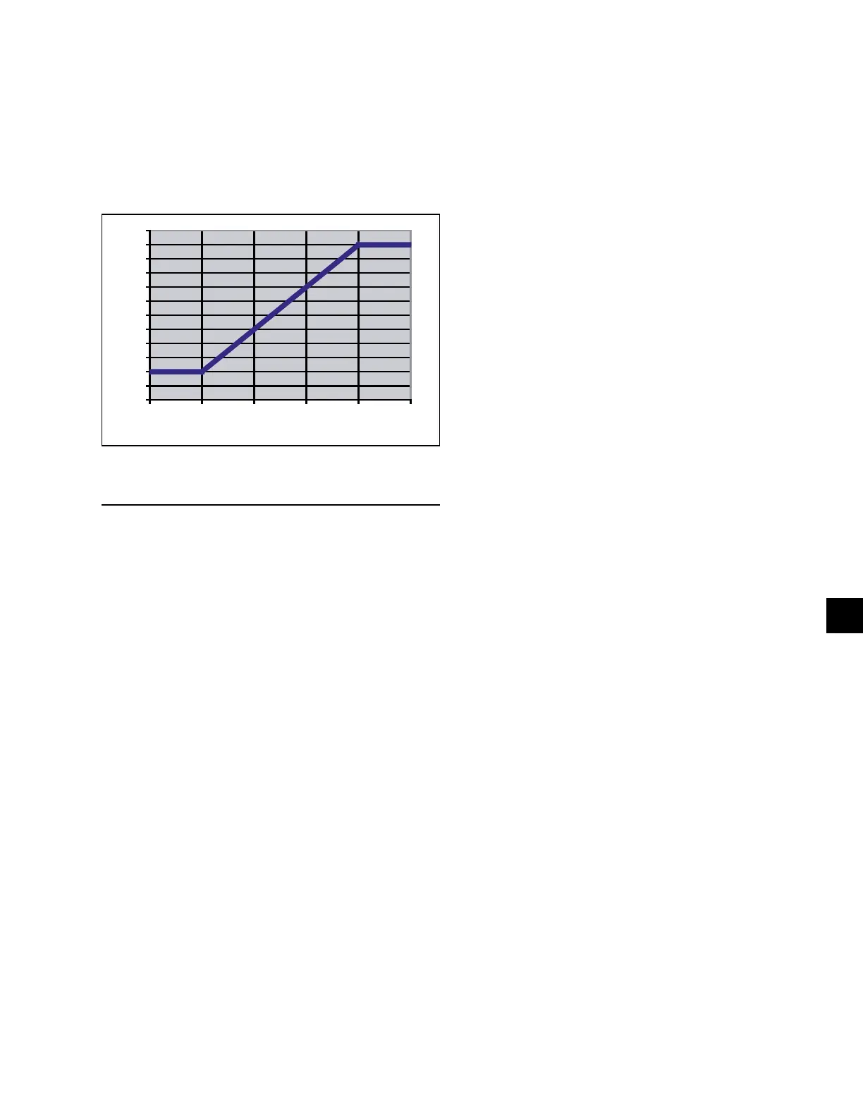
• If the ambient is between 110 and 125°F (43 and
52°C), the Minimum VSD Run Frequency is
scaled according to the following formula:
(3 x Ambient Temperature) - 280°F.
The formula is also represented by the graph in Figure
52 on page 201.
NOTE: The graph above also illustrates the scaled frequency:
FIGURE 52 - MINIMUM VSD RUN FREQUENCY
LD10628
40
45
50
55
60
65
70
75
80
85
90
95
100
105 110 115 120 125 130
Ambient Temperature (°F)
Mini mum VSD Frequency (Hz)
• If the ambient temperature is more than 125°F, the
Minimum VSD Run Frequency will be 95 Hz.
ACCELERATION / DECELERATION
RATE WHEN STARTING / STOPPING
COMPRESSORS
VSD Acceleration and Deceleration Rates
The acceleration rate changes with frequency and fol-
lows the guidelines below:
• Between 0 Hz and 50 Hz, the acceleration is 10
Hz/s.
• Between 50 Hz and 200 Hz, the acceleration is
30.4 Hz/s. Even though the acceleration rate of
30.4 Hz/s is possible up to 200 Hz, the frequency
(speed) is limited by the minimum start frequency
and the add a compressor frequency calculation
performed by the microprocessor when bringing
on an additional compressor.
When decelerating, the deceleration rate changes with
frequency and follows the guidelines below:
• Between 200 Hz and 100 Hz, the deceleration
time is 30.4 Hz/s.
• Between 100 Hz and 0 Hz, the deceleration time
is 10 Hz/s.
When a compressor stops, back-spin of the compres-
sor will often occur as the pressure differential between
discharge and suction equalizes. This should not be a
cause of concern.
STANDARD IPLV CAPACITY CONTROL
(Loading/Unloading and starting additional compressors)
Standard IPLV Capacity Control is installed in the
chiller at the factory using a dedicated EPROM (soft-
ware), part # 031-02476-001, for “Standard Only”
IPLV control. If the LCHLT is more than the pro-
grammed Setpoint plus CR, only a single compressor
is permitted to start under Standard IPLV control. The
compressor will start at the minimum start frequency
based on ambient temperature (Page 214). The lead
compressor Feed and Drain Valves will immediately
begin to control superheat and liquid level in the flash
tank.
When a compressor starts, the load and unload timers
will be set to 30 seconds. During the first 30 seconds
of operation after a compressor reaches the start fre-
quency, loading/unloading is inhibited.
After 30 seconds, the control logic looks at the LCHLT
temp, compares it to the Setpoint plus CR, and makes
decisions to load or unload.
For precise capacity control, the Chiller Control Board
microprocessor loads and unloads compressors quick-
ly, as fast as every 2 seconds, in increments of 0.1 to
1 Hz each time a load or unload change is required.
Fixed load and unload timers of 2 sec. are set, after a
speed change of 0.11 to 1 Hz, to minimize undershoot
and overshoot.
As additional cooling is required (LCHLT more than
Setpoint plus CR), the Chiller Control Board micro-
processor will increase the speed of the compressor at
the rate of 0.1 Hz to 1 Hz every 2 seconds until the load
is satisfied. Loading will continue to occur as long as
leaving chilled liquid temperature is above the Setpoint
plus CR.
If the temperature falls very near or within the Control
Range, the Chiller Control Board microprocessor will
make decisions regarding speed changes under condi-
tions where the “error” and “rate” conflict. Under these
conditions, loading/unloading follows the guidelines
described in the Fuzzy Logic Control on page 205.

 Loading...


