JOHNSON CONTROLS
100
FORM 161.01-OM1
ISSUE DATE: 6/8/2018
SECTION 3 - OPTIVIEW™ CONTROL CENTER FUNCTIONS AND NAVIGATION
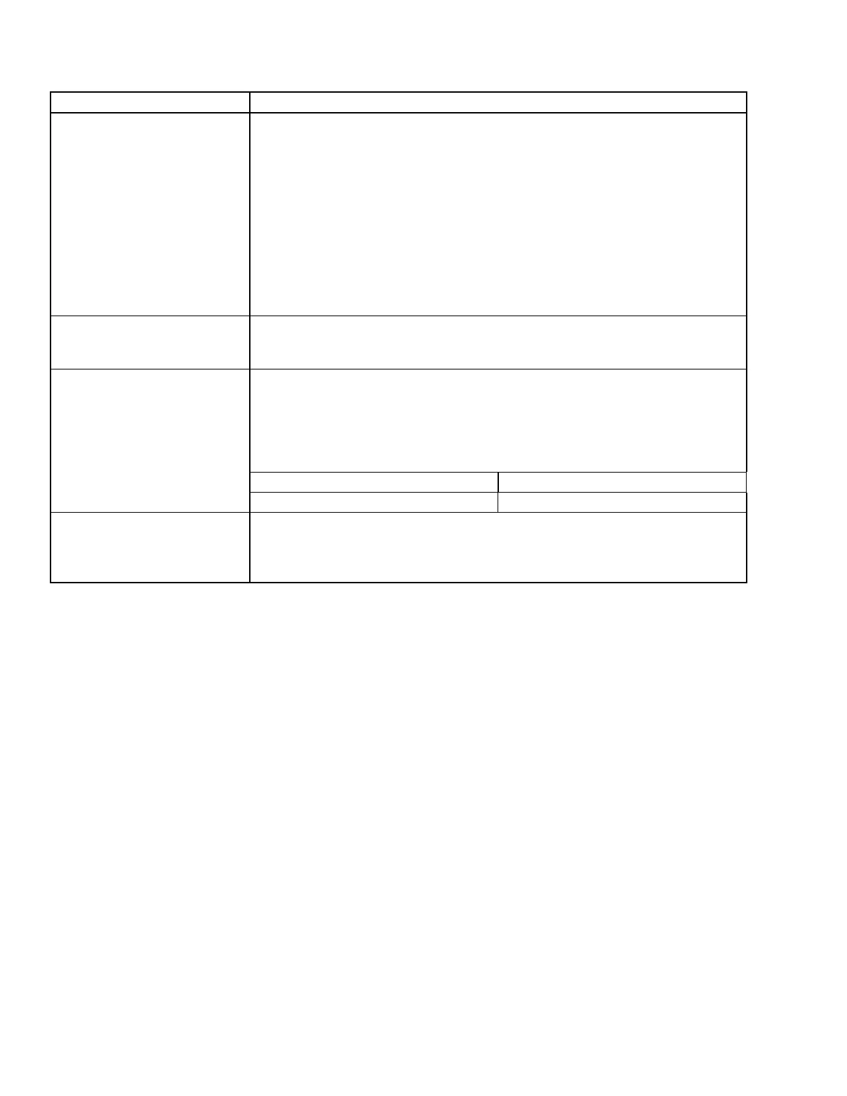
TABLE 11 - CYCLING SHUTDOWN MESSAGES (CONT'D)
MESSAGE DESCRIPTION
HARMONIC FILTER – LOW DC
BUS VOLTAGE
The harmonic lter dynamically generates its own lter DC bus voltage by the interac-
tion of the harmonic lter inductor and switching the power devices in the harmonic lter
power unit. This DC level is actually higher than the level obtained by simply rectifying
the input line voltage.
NOTE: The DC link voltage is always higher on the harmonic filter power unit than
on the VSD power unit.
Thus, the harmonic lter actually performs a voltage “boost” function. This is neces-
sary in order to permit current to ow into the AC line from the harmonic lter when the
AC line is at its peak level. This particular shutdown and its accompanying message
are generated when the harmonic lter’s DC link voltage drops to a level less than 80
VDC (for 380 through 460 VAC input voltage) below the harmonic lter DC link voltage
setpoint.
HARMONIC FILTER – PHASE
LOCKED LOOP
This shutdown indicates a circuit called a “phase locked loop” on the harmonic lter
logic board has lost synchronization with the incoming power line for a period of time.
This message may also appear when utility power is removed and reapplied
HARMONIC FILTER –
PRECHARGE LOW DC BUS
VOLTAGE 1 (OR 2)
Two minimum voltage thresholds must be met in order to complete the precharge cycle.
The rst occurs 1/10th of a second after pre-charge is initiated. This measurement will
verify the bus structure, or bus capacitors are not damaged. The second threshold
occurs 5 seconds after precharge is initiated. This measurement will verify the bus
capacitors are charging properly. See table below for specic values of a Nominal Input
Voltage Value of 380-460 VAC.
1ST MINIMUM VOLTAGE VALUE 2ND MINIMUM VOLTAGE VALUE
41 VDC 630 VDC
HARMONIC FILTER – Run
Signal
When a hardware run command is received at the harmonic lter logic board from the
drive logic board, a 5 second timer is started. A redundant run command must also oc-
cur on the communication link from the drive logic board before the timer expires or the
drive will be shut down.
 Loading...


