JOHNSON CONTROLS
99
SECTION 3 - OPTIVIEW™ CONTROL CENTER FUNCTIONS AND NAVIGATION
FORM 161.01-OM1
ISSUE DATE: 6/8/2018
3
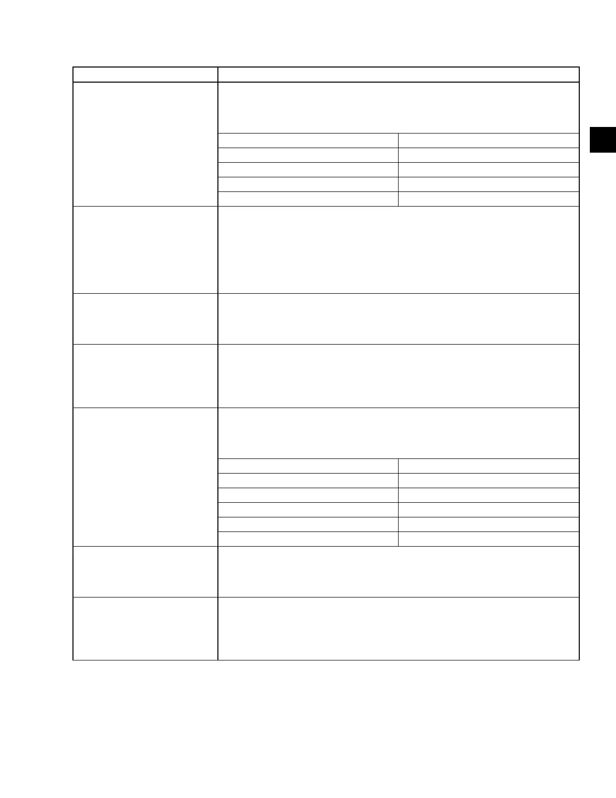
MESSAGE DESCRIPTION
HARMONIC FILTER – INPUT
CURRENT OVERLOAD
The three phases of RMS lter current are measured by the lter DCCTs’. This informa-
tion is sent to the harmonic lter logic board. If any one phase of lter current exceeds a
threshold for 40 seconds a shutdown will occur. Refer to the chart below for the shut-
down threshold
DRIVE CURRENT RATING NOMINAL PEAK TRIP LEVEL
330/420 128 AMPS RMS
780 176 AMPS RMS
1020 278 AMPS RMS
1280 385 AMPS RMS
HARMONIC FILTER – DC BUS
VOLTAGE IMBALANCE
The DC link is ltered by many large capacitors. These capacitors are connected in
series to achieve a higher DC link voltage then can be supported by a single capacitor.
It is important that the voltage is shared equally between the two sets of series capaci-
tors. Each set of capacitors must share approximately 1/2 of the total DC link voltage.
The harmonic lter logic board then measures the voltage of the 2 sets of the bus
capacitors. If at any time while the harmonic lter is running the difference in the voltage
between the 2 sets of capacitors is greater than 50 VDC then a shutdown will occur.
HARMONIC FILTER – DC
CURRENT TRANSFORMER 1
(OR 2)
During initialization, with no current owing through the direct current current transduc-
ers (DCCT’s), the DCCT’s output current are measured and compared to a preset limit
dened by the harmonic lter logic board. If the measured values exceed the preset
limit, the DCCT’s are presumed to be bad and this shutdown will be generated.
HARMONIC FILTER – HIGH DC
BUS VOLTAGE
The harmonic lter logic board continuously monitors the harmonic lter DC bus volt-
age. If the level of the DC bus voltage exceeds a range of 822 to 900 VDC this shut-
down is initiated. Keep in mind that the harmonic lter has its own DC bus as part of the
harmonic lter power unit. The harmonic lter DC bus is not connected in any way with
the drive’s DC bus.
HARMONIC FILTER – HIGH
PHASE A (OR B, C) CURRENT
The output current of the harmonic lter is read by the Direct Current-Current Trans-
ducer (DCCT). This current information is sent to the harmonic lter logic board where it
is compared against a threshold. If the output current of the harmonic lter power unit is
greater than the threshold..
DRIVE CURRENT RATING NOMINAL PEAK TRIP LEVEL
330 270 ± 25 AMPS Pk
420 378 ± 59 AMPS Pk
780 523 ± 84 AMPS Pk
1020 782 ± 118 AMPS Pk
1280 1274 ± 104 AMPS Pk
HARMONIC FILTER – LOGIC
BOARD OR COMMUNICATIONS
This shutdown states the hardware on the harmonic lter logic board is indicating
a fault, but the software on the harmonic lter logic board does not state why. The
harmonic lter logic board signals a fault condition to the drive logic board but does not
respond to a software request for fault information.
HARMONIC FILTER – LOGIC
BOARD POWER SUPPLY
This shutdown indicates one of the low voltage power supplies on the harmonic lter
logic board have dropped below their permissible operating voltage range. The harmon-
ic lter logic board receives its power from the drive logic board. The power supplies for
the drive logic board are in turn derived from the secondary of the 120 to 24 VAC trans-
former. This fault is typical when control power to the board is removed and reapplied.
TABLE 11 - CYCLING SHUTDOWN MESSAGES (CONT'D)
 Loading...


