JOHNSON CONTROLS
98
FORM 161.01-OM1
ISSUE DATE: 6/8/2018
SECTION 3 - OPTIVIEW™ CONTROL CENTER FUNCTIONS AND NAVIGATION
MESSAGE DESCRIPTION
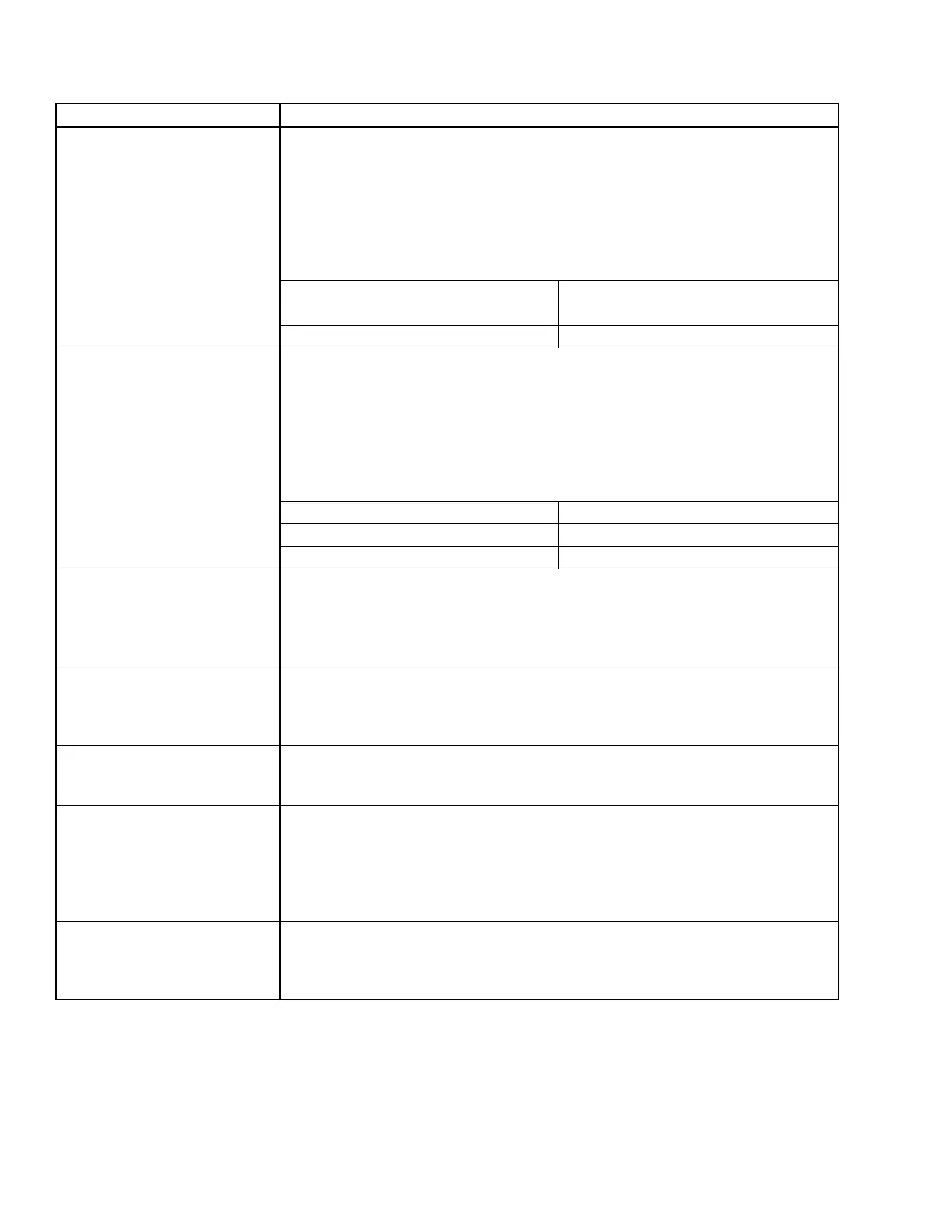
VSD – PRECHARGE – LOW DC
BUS VOLTAGE 1
During Pre-charge, the dc-link voltage must reach at least low threshold which is
determined by Line Voltage Setpoint (see the table below) within 4 seconds after the
pre-charge signal has been commanded. If this condition is not met, this shutdown is
generated. The VSD logic board shall time 10 seconds before clearing the fault and
allowing another pre-charge to start. The VSD’s fan(s) and water pump(s) shall remain
energized during this time. The VSD logic board shall allow up to three consecutive
pre-charge-related faults to occur. After the third consecutive pre-charge-related fault,
Safety Shutdown message “VSD – PRECHARGE LOCKOUT” is generated.
LINE VOLTAGE LOW THRESHOLD (VOLTS)
380/400/415 41
460 50
VSD – PRECHARGE – LOW DC
BUS VOLTAGE 2
During Pre-charge, the DC-link voltage must reach at least high threshold which is
determined by Line Voltage Setpoint (see the table below) within 20 seconds after the
pre-charge signal has been commanded. If this condition is not met, this shutdown is
generated. The VSD logic board shall time 10 seconds before clearing the fault and
allowing another pre-charge to start. The VSD’s fan(s) and water pump(s) shall remain
energized during this time. The VSD logic board shall allow up to three consecutive
pre-charge-related faults to occur. After the third consecutive pre-charge-related fault,
Safety Shutdown message “VSD – PRECHARGE LOCKOUT” is generated.
LINE VOLTAGE LOW THRESHOLD (VOLTS)
380/400/415 414
460 500
VSD – RUN SIGNAL
Redundant RUN signals are generated by the control center; one via TB6-24 and the
second via the Serial Communications link. If both run commands are not received by
the VSD Logic Board within 5 seconds, a shutdown is performed and this message is
displayed. This is generally indicative of a wiring problem between the control center
and the VSD.
VSD – SERIAL RECEIVE
This message is generated when communications between the micro board and the
drive logic board is disrupted for a least 22 seconds. If the optional Harmonic Filter is
installed then the fault can be generated when the communications between the drive
logic board and the Harmonic Filter logic board is disrupted.
VSD – SINGLE PHASE INPUT
POWER
The VSD monitors the RMS value of each of the three line-to-line voltages on a cycle-
by-cycle basis If the RMS value of any one of the three line-to-line voltages falls below
230 Vrms in any 1/2 cycle, this shutdown is generated.
VSD – STOP (FAULT)
CONTACTS OPEN
Whenever the drive initiates a fault, it rst opens the fault relay on the drive logic board.
When the relay opens a message is sent to control panel's micro board, detailing the
cause of the fault. If this circuit ever opens without receiving an accompanying cause for
the fault over the communication link (within 11 communication tries, approximately 22
seconds) this message will be displayed. This fault may be replaced with a Serial Com-
munications fault if the serial link has failed.
VSD – INVALID PWM
SOFTWARE
On power up the main processor shall communicate the software type (LP, HP or
production) to the PWM processor. The PWM processor shall then conrm that it has
the corresponding software installed. If this condition is not met the unit shall trip on an
invalid PWM software fault.
TABLE 11 - CYCLING SHUTDOWN MESSAGES (CONT'D)
 Loading...


