JOHNSON CONTROLS
97
SECTION 3 - OPTIVIEW™ CONTROL CENTER FUNCTIONS AND NAVIGATION
FORM 161.01-OM1
ISSUE DATE: 6/8/2018
3
MESSAGE DESCRIPTION
VSD – HIGH DC BUS VOLTAGE
The DC bus voltage is continuously monitored and a shutdown will occur if the DC bus
voltage exceeds 737-795 VDC. This shutdown will protect the capacitors from a voltage
that exceeds their rating.
VSD – HIGH INTERNAL
AMBIENT TEMPERATURE
The ambient temperature of the drive is monitored by a temperature sensor mounted on
the drive logic board. The high ambient trip threshold is 122°F (50 °C) for all models. If
this fault occurs, the fans and coolant pump/s will remain on until the internal ambient
temperature has fallen to 115°F (46 °C).
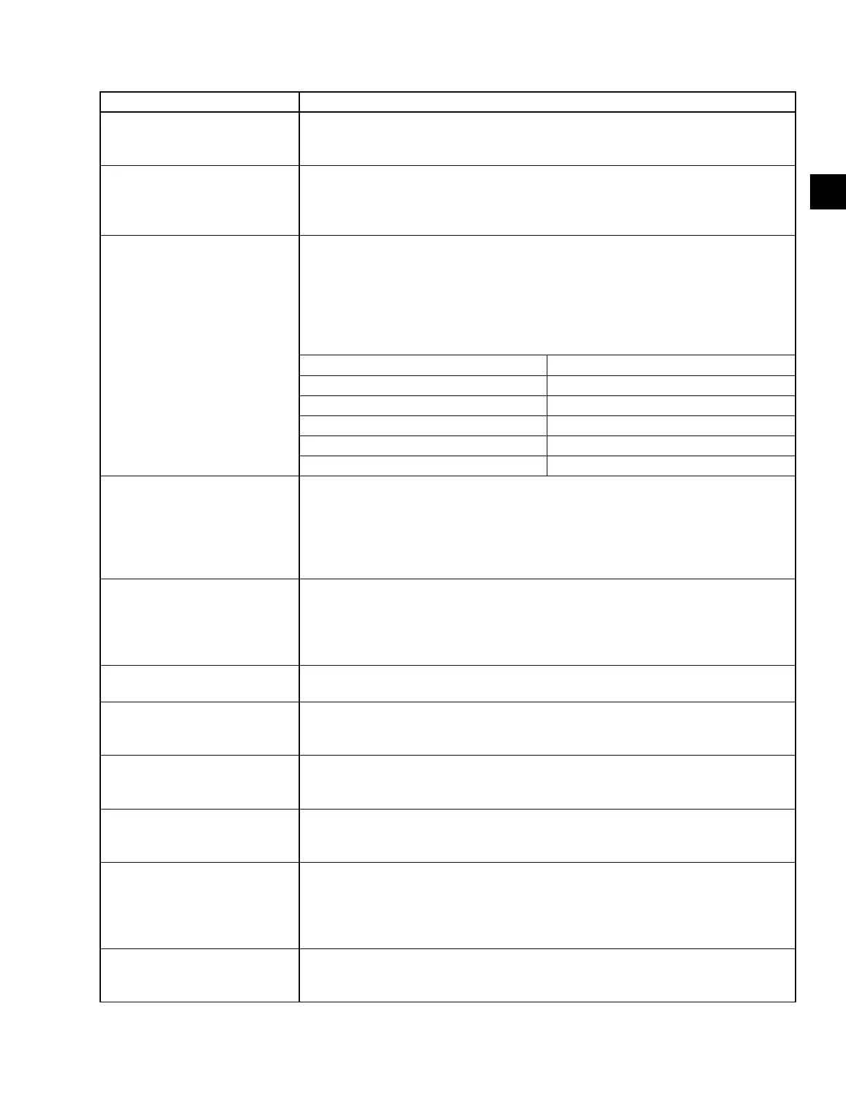
VSD – HIGH PHASE A (OR B, C)
INSTANTANEOUS CURRENT
This shutdown is generated by the drive logic board. If any one phase of motor current
as measured by the Output Current Transformers exceeds a threshold. Refer to the
chart below for the shutdown threshold value. If an Instantaneous Current Fault occurs
but the chiller restarts and runs without a problem, the cause may be attributed to a volt-
age sag on the utility power feeding the drive that is in excess of the specied dip volt-
age rating for this product. This is especially true if the chiller was running at, or near,
full load. If there is a sudden dip in line voltage, the current to the motor will increase.
DRIVE AMP RATING NOMINAL PEAK TRIP LEVEL
330A 773 Amps Peak
420A 773 Amps Peak
780A 1890 Amps Peak
1020A 1890 Amps Peak
1280A 2406 Amps Peak
VSD – INVALID VSD MODEL
The J1 connector on the drive logic board contains jumpers along with wires from the
output CTs. The jumpers congure the drive logic board to the output current rating of
the drive being used in this application in order to properly scale the output current. If
the jumper conguration is found by the logic board to be invalid, the system will be shut
down and the above message will be generated. The proper jumper conguration is
shown on the wiring label for the drive.
VSD – LOGIC BOARD POWER
SUPPLY
This shutdown is generated by the VSD logic board and it indicates that the low voltage
power supplies for the logic board have dropped below their allowable operating limits.
The power supplies for the logic boards are derived from the secondary of the 120 to
24VAC transformer, which in turn, is derived from the line to 120VAC control power
transformer. This message usually means the power to the VSD has been removed.
VSD – LOGIC BOARD
PROCESSOR
This shutdown is generated by the drive logic board. If a communications problem oc-
curs between the two microprocessors on the drive logic board this shutdown will occur.
VSD – LOW CONVERTER
HEATSINK TEMPERATURE
A thermistor sensor is located on the SCR/Diode block side of the copper chill plate on
the DRIVE Power Unit. Anytime this thermistor detects a temperature of 37 °F (3 °C) or
lower a shutdown will occur.
VSD – LOW DC BUS VOLTAGE
Following a successful DC link pre-charge and pre-regulation, the DC link under-voltage
shutdown is generated when the DC link voltage falls below the trip level for 10 ms. The
trip level is set to 500 VDC for 460 VAC and 414 VDC for 400/380 VAC unit.
VSD – LOW INVERTER
BASEPLATE TEMPERATURE
A thermistor sensor is located inside the transistor module(s) on the drive power unit.
Anytime this thermistor detects a temperature of 37 °F (3 °C) or lower a shutdown will
occur.
VSD – PHASE A (B or C) GATE
DRIVER
A second level of overcurrent current protection exists on the drive gate driver board.
The collector-to-emitter voltage of each transistor module is checked while the device is
turned on. This is called the collector-to-emitter saturation voltage. If the voltage across
the transistor module is greater than a set threshold, the transistor module is turned off.
This fault can also be caused if the transistor is not being turned on when it should.
VSD – PRECHARGE - DC BUS
VOLTAGE IMBALANCE
The denition for this fault is identical to “VSD - DC Bus Voltage Imbalance” except the
fault occurred during the precharge period. Refer to “VSD - DC Bus Voltage Imbalance”
shutdown for possible problems.
TABLE 11 - CYCLING SHUTDOWN MESSAGES (CONT'D)
 Loading...


