Owner’s Manual | PCAS XRX
STRENGTHS AND LIMITATIONS 33
The true effect of this is a limitation in overall detection, not a
reduction in bearing quality. An example of this effect is an aircraft
at 3.0 NM would indicate 6.0 NM, or an aircraft at 0.5 NM would
indicate 1.0 NM. It is a common misconception that multipath
propagation that can occur when an RF signal takes different
paths around this type of blockage when propagating from the
source to the destination. This propagation has no effect on
bearing quality, meaning that the tail section of your aircraft will
not force an incorrect bearing from the target aircraft.
If your aircraft type is composite, you will not notice this anomaly.
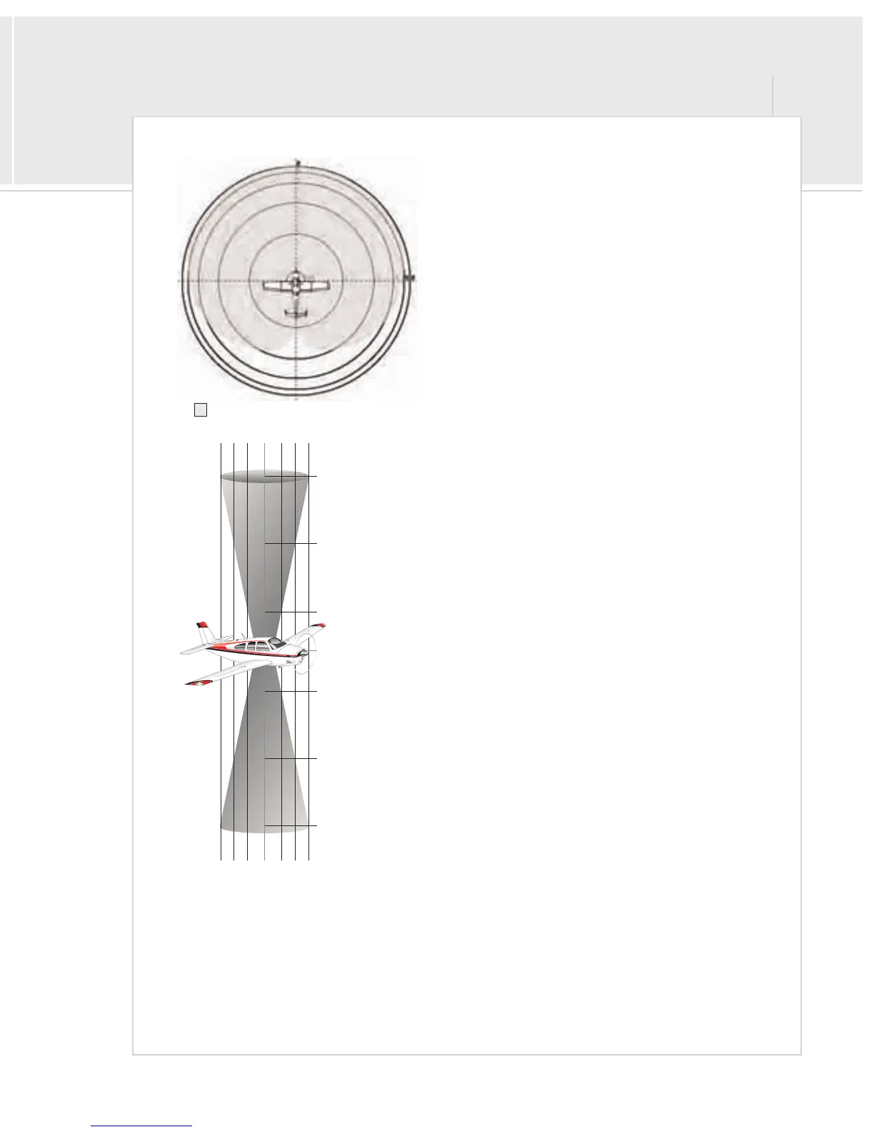
Cones of Confusion
At the point where the transmitting signal is either directly above
or below your aircraft, cone-shaped areas exist above and below
your aircraft in which the directional sensing ability becomes
uncertain.
These cones, illustrated here, are similar in appearance and
function to the cones of confusion that exist around VORs. These
areas of ambiguity become larger the greater the vertical separa-
tion. An aircraft entering into these areas of ambiguity may
momentarily show up as from more than one direction. In other
words, more than one directional arrow may be displayed. As soon
as the aircraft passes through, the new direction will be acquired
and accurately displayed once again.
The less vertical separation exists between you and the target
aircraft, the greater the accuracy of the bearing information. In
other words, aircraft close to your altitude are easier to determine
their bearing. Aircraft at a high angle to you approach the cone of
confusion.
Typical Detection Window (High Wing)
0.7 NM +2000 ft.
+1000 ft.
+500 ft.
+500 ft.
+1000 ft.
+2000 ft.
|
|
|
|
|
|
|
|0.7 NM
0.5 NM
0.5 NM
0.2 NM
0.2 NM


 To Next Page