Formats
165
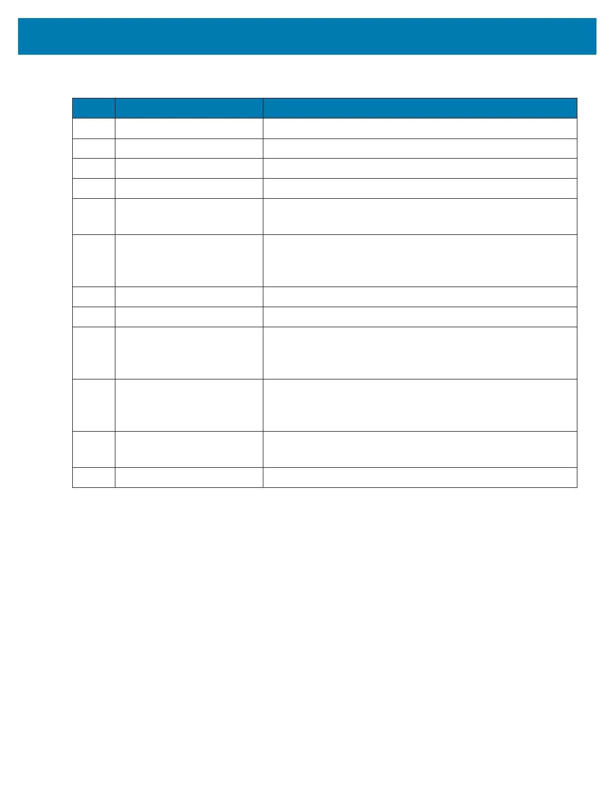
Table 14 I/O Connector Pin-Outs
Pin Signal Description
1 GND Ground
2 DETECT Detects connected accessory.
3 RX UART Rx signal (scanner).
4 PWR_OUT Power output (scanner).
5 USB_PWR
PWR_OUT
USB VBUS Power (cradles).
Power output (scanner and vibrator cable).
6 USB_ID
UART_CTS
MIC
USB ID pin (cradles).
UART_CTS (scanner).
Microphone input (wired headset).
7 PWR_IN Input power (cradles).
8 PWR_IN Input power (cradles).
9TX
SPEAKER
VIBRATOR
UART Tx signal (cradles and scanner).
Audio out (wired headset).
Vibrator control signal (vibrator).
10 USB_D+
HW_TRIG
PTT
USB Data D+ (cradles)
Scan trigger detect (scanner).
Push-to-Talk signal (wired headset).
11 USB_D-
UART_RTS
USB Data D- (cradles)
UART RTS signal (scanner).
12 GND Ground