ILLUSTRATIONS
Stemi DV4 / DR Carl Zeiss
B 40-003 e 08/00 0-5
ILLUSTRATIONS
Page
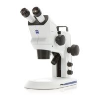
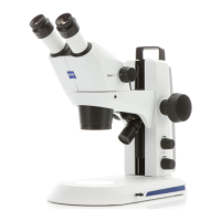
Fig. 2-1 Stemi DV4 / DR microscope body.................................................................................2-1
Fig. 2-2 System diagram of compact version with stand C........................................................2-2
Fig. 2-3 Interfaces of Stemi DV4 / DR with stand C (schematic).................................................2-3
Fig. 2-4 Stemi DV4 / DR system diagram within the Zeiss Stemi modular system........................2-6
Fig. 2-5 Interfaces of the Stemi DV4 / DR with column-type stand (schematic)..........................2-7
Fig. 2-6 Front lenses of Stemi DV4 / DR....................................................................................2-7
Fig. 3-1 Installation and mains connection of the Stemi DV4 / DR..............................................3-1
Fig. 3-2 Operation and function controls on the Stemi DV4 / DR...............................................3-2
Fig. 3-3 Illumination control.....................................................................................................3-3
Fig. 3-4 Basic settings (Stemi DV4) ...........................................................................................3-5
Fig. 3-5 Changing the lamp (reflected light) .............................................................................3-7
Fig. 3-6 Changing the lamp (reflected light) .............................................................................3-7
Fig. 3-7 Removing the glass plate.............................................................................................3-8
Fig. 3-8 Changing the lamp (transmitted light).........................................................................3-8
Fig. 3-9 Inserting the glass plate...............................................................................................3-9
Fig. 3-10 Setting the smoothness of the focusing drive...............................................................3-9
Fig. 3-11 Removing the glass plate...........................................................................................3-10
Fig. 3-12 Insertion of transmitted-light darkfield attachment.....................................................3-10
Fig. 3-13 Insertion of eyepiece measurement device.................................................................3-11
Fig. 3-14 Eyepiece micrometer 8x/32x/18.................................................................................3-11
Fig. 3-15 Attachment of SLR camera........................................................................................3-12
Fig. 3-16 Attachment of SONY camera "Digital Handycam DCR-PC100"..................................3-13
Fig. 3-17 Attachment of SONY camera "Digital Still Camera Cybershot DSC-F505" ..................3-14
Fig. 3-18 Attachment of SONY camera "Digital Still Camera Cybershot DSC-S70"....................3-15
Fig. 3-19 Attachment of video camera with C-Mount connector..............................................3-17
Fig. 3-20 Attachment of microhead camera.............................................................................3-17
Fig. 3-21 Attachment of insertion camera ................................................................................3-18