28.
Damage due to wrong arrangement of the
par
ts possible.
ð
Observe installation position of the
individual parts.
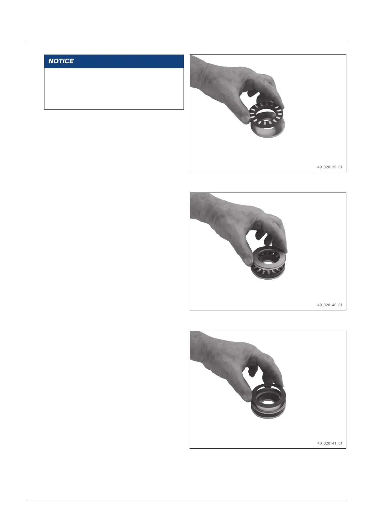
Put the roller cage onto the shaft washer.
Radius or chamfer on the internal diameter of
the shaft washer must be opposite of the
roller cage.
Fig. 214
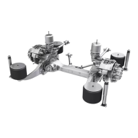
29. Place disk with radius or chamfer on the
out
er diameter showing upwards onto the
roller cage.
Fig. 215
30. Place cup spring with the concave side
sho
wing downwards onto the disk.
Fig. 216
Assembly
EN 4472.751.001 - 2015-11
109