Factory setting: E1 min. = 5 %, E1 max. = 100 %
0.5...10 V
0...100 % speed setting
I.e. the motor starts with 6 % of the rated speed at a setting signal of approx. 1 V.
Example: E1 min. = 0 %, E1 max. = 100 %
0....10 V
0...100 % speed setting
Example: E1 min. = 0 %, E1 max. = 50 %
0....5 V
0...100 % speed setting
5.10 Voltage supply “10 V DC”
Voltage supply for activation of the digital input and external components, e.g. for a potentiometer for
speed setting (PELV current source according to EN 60204-1).
Connection: “10 V” - “GND” (max. load
Technical data und connection diagram).
During an overload or short-circuit (10 V - GND), the control voltage (and thus the device) is
disconnected . Automatic start after elimination of the cause of error.
It is not permissible to connect outputs of several devices to each other!
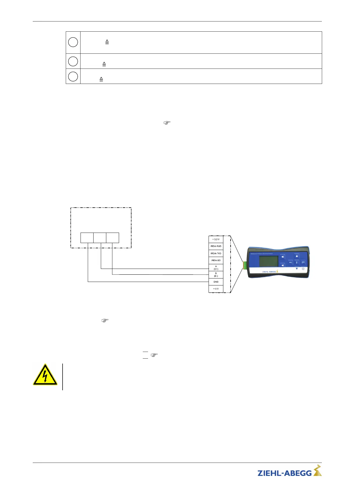
5.11 Connection terminal type A-G-247NW for service
If necessary an external terminal can be connected. This can be e.g. necessary to adapt the pre-
setting during start-up.
The connection is made by a 4-wire cable at the terminals: A (D+), B (D-) and GND. E. g. telephone
cable type: J-Y (St) Y 2x2x0.6 (or similar), maximum cable length approx. 250 m.
The voltage supply of the terminal is made by the accumulators inserted there or the plug power
supply unit.
13.05.2013
v_a-g-247nw_at_ecblue.vsd
GND
A
(D+)
B
(D-)
A-G-247NW
5.12 Digital input “D1” for enable (device ON / OFF)
Electronic ON / OFF control via floating contact at terminals “+10V” - “D1” (input resistance and
voltage range
Technical data).
Function factory setting for “D1”:
•
Device “ON” for closed contact.
•
Device “OFF” with opened contact.
Relay “K1” remains energized, connections 11 - 14 bridged.
Status Out with flash code:
|
1
|
(
Diagnostics / Faults).
Danger due to electric current
•
No disconnection (no potential isolation in accordance with VBG4 §6) in remote control of the
device!
•
Never apply line voltage to the digital input!
5.13 Relay output “K1” for fault indication
An external fault indicator is available over the potential-free contact of the built-in relay (max. contact
rating see Technical data and connection diagram).
Function factory setting for “K1”:
•
For operation the relay is energized, connections “11” and “14” are bridged. For fault the relay is de-
energized (see Diagnostics / Faults).
•
When switching off via enable (D1 = Digital In 1), the relay remains energized.
Assembly instructions ECblue Electrical installation
L-BAL-F055D-GB 2021/51 Index 006 Part.-No.
23/56

 Loading...